background image

TM/ RM-1327GE Series 


34


Hardware Installation


7.2.4


Attaching the Camera Lens 

The TM-1327GE camera accepts 2/3” or larger format size C-mount lenses. To attach the C-mount 
lens1

2

 to the camera, carefully engage the threads and rotate the lens clockwise until it firmly seats 

on the mounting ring. Do not force the lens if it does not seat properly. 

Note:  Some lenses with extremely long flangebacks may exceed the mounting depth of the camera. 

7.2.5


Adjustable Back-Focus 

Before cameras are shipped, back focus is carefully set using a collimator, oscilloscope and other 

specialized equipment. While the factory-set focus serves well in most cases, an adjustable back 
focus makes it possible to improve image sharpness when using lower-cost zoom lenses, custom 

optics, or in unusual parameters. 

There should be an obvious need to refocus the lens before attempting to change the back focus. 

This is a very exacting task. Some cameras have been returned to the factory to reset the back 
focus after failed attempts to change the focus by customers. It might be wise to label cameras 

whose back focus was adjusted 

1.  The camera must be connected to a monitor before attempting to adjust the back focus. 

2.  To back focus the camera, first attach a C-mount lens in the mount. Be certain that the lens is 

properly seated. 

3.  Next set the lens focus to infinity (if the lens is a manual iris, set the iris to a high f number 

while still retaining a well illuminated image). 

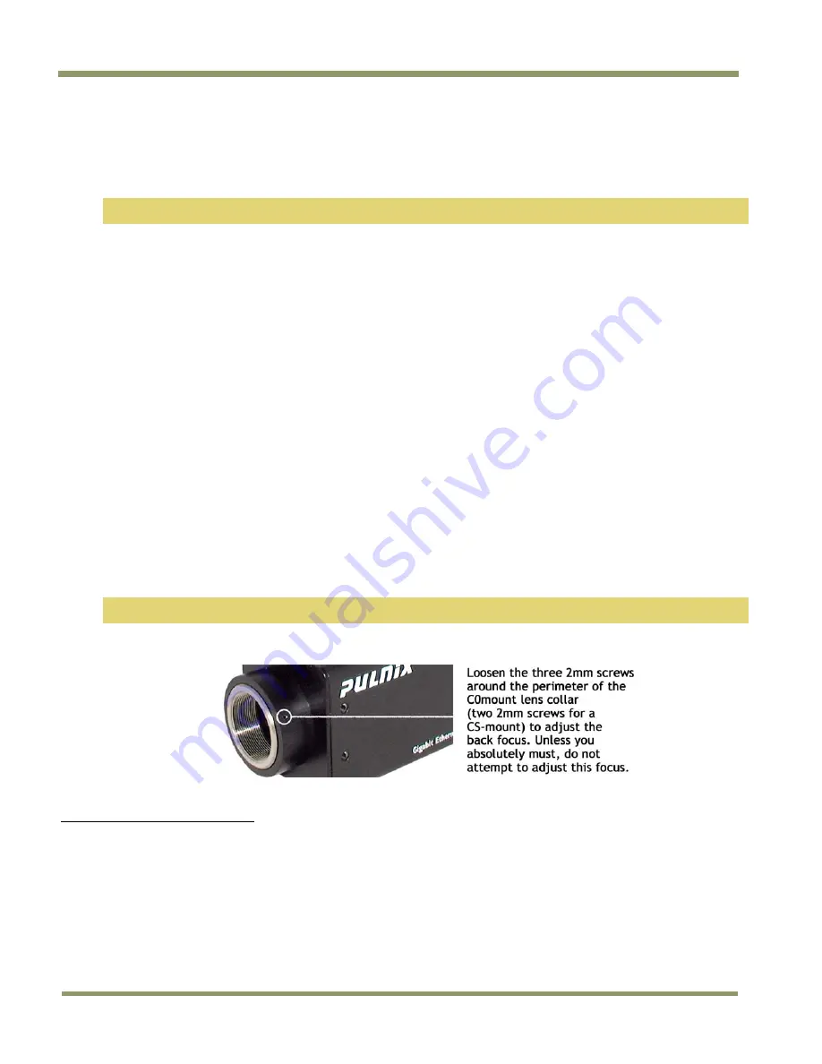
4.  Loosen the three miniature hex set-screws (use a 0.9 mm hex wrench) that lock the focus ring 

in place (two screws for a CS-mount). Slowly turn the lens and focus ring assembly back and 
forth until you obtain the best image of the desired object. This sets the back focus. Once the 

best image is obtained, tighten the focus ring set-screws until they are snug. Do not over-
tighten the screws. 

Note: Mini-bayonet cameras adapted to C-mount do not have the back focus feature. 

Figure 29.


Back-Focus Set-Screw Locations  


2

 C-mount to F-mount and C-mount to K-mount adapters are available for larger format lenses (35mm). Check with local 

photography dealers for these lens adapters. 

Summary of Contents for TM-1327GE Series

Page 1: ...TM RM 1327GE Series Digital Monochrome Color Progressive Scan Interline Transfer Gigabit Ethernet Camera Document Version E Document P N 10164...

Page 2: ......

Page 3: ...A2 2003 Immunity EN55024 1998 A1 2001 A2 2003 All JAI products bearing the CE mark have been declared to be in conformance with the applicable EEC Council Directives However certain factory installed...

Page 4: ...ed by the party responsible for FCC compliance could void the user s authority to operate the equipment TM 1327GE Series Operation Manual JAI Inc 625 River Oaks Parkway San Jose CA 95134 Tel 408 383 0...

Page 5: ...Notice v TM RM 1327GE Series February 12 2008...

Page 6: ...TM RM 1327GE Series vi Table of Contents Table of Contents Disclaimer Notice iii Table of Contents v List of Figures vii List of Tables ix...

Page 7: ...List of Figures vii TM RM 1327GE Series List of Figures...

Page 8: ...TM RM 1327GE Series viii List of Figures...

Page 9: ...List of Tables ix TM RM 1327GE Series List of Tables...

Page 10: ...TM RM 1327GE Series x List of Tables...

Page 11: ...dded to your system when the software is installed 1 3 Gigabit Ethernet Camera Interface The GigE interface provides an easily connectable high bandwidth imaging solution where video data is sent as I...

Page 12: ...r GigE_Software and run the setup bat file This installs the GigE camera software as part of the Camera Interface Application It copies the file cycampulnix dll to the folder C Program Files JAI Cam2N...

Page 13: ...Connect the camera The Hirose pin layout is shown in Table 1 on page 6 Both the Hirose and the network cable RJ 45 are illustrated in Figure 6 2 Run the Camera Interface Application 3 Click Detect Ass...

Page 14: ...ake sure the camera is set to the proper color space and pixel depth then click the check box labeled Use 3 x 3 Bayer Interpolation in the Conversion Options panel More information on color interpolat...

Page 15: ...ction of each pin The table lists the GPIO assignments for the relevant pins A magnified illustration of each pin s assignment follows in Figure 7 on page 7 Table 1 Hirose Connector Pin Assignment Pin...

Page 16: ...cat5e UTP cables Cat6 cables are preferred If you wish to connect the camera directly to a PC you must use a cross over cable Refer to the Cam2Net User s Manual for details 1 Figure 8 Ethernet GigE S...

Page 17: ...e the following steps 1 Start the Camera Interface Application The dialog box shown in Figure 9 appears 2 Click the Detect to detect the device and driver in the Device Actions panel 3 Click Select Ca...

Page 18: ...or other cameras 3 4 Modes This section includes several examples of setup actions available through the camera configuration dialog box Note that items 3 4 2 through 3 4 8 are all found under the Gig...

Page 19: ...vertical direction Figure 16 Scan Mode screen shot 3 4 4 Gain Settings The Gain Settings control box shown in Figure 17 allows you to change the Gain value from 3dB to 12dB To change the value move th...

Page 20: ...ly The Table Selection pull down menu allows you to select the Linear or Gamma 45 option This control also allows you to check the positive or negative image option 3 4 7 Memory Pages All the camera p...

Page 21: ...the GPIO look up table to Q4 I0 and Q5 1 3 4 10 Internally Triggered The camera control software includes pulse generators that you can use to trigger the camera internally To do this use the followin...

Page 22: ...d B channels If you choose to assign custom values click Apply Results Figure 21 White Balance Control Settings screen shot 3 4 13 Main Menu Option The Grabber Settings tabbed dialog box has a check b...

Page 23: ...equired to support specific camera functions refer to Asynchronous Reset on page 42 The TM 1327GE has three externally controllable standard signals Trigger VINIT or EXT_TRIG CC1 equivalent VD in EXT_...

Page 24: ...PIO Look Up Table screen shot Figure 24 The GPIO Configuration screen shot 4 3 GPIO Label Tables Table 2 shows which GPIO inputs carry the different signals The top line for each label contains the de...

Page 25: ...These generators can run as either periodic or triggered To run the pulse generators as triggered they can be triggered on either levels or signal edges These generators can be tied to the camera inpu...

Page 26: ...0 cr Set Async Direct Shutter DDD 000 81F Data Output Control DDP N cr o cr Set output data depth N 0 8 bit N 1 10 bit Lookup Table LINR cr o cr Set linear table GM45 cr o cr Set gamma 45 table KNEE...

Page 27: ...de0 000 Manual Shutter 001 Async Shutter 010 Async Direct Shutter 011 Direct Shutter Bit 4 Output Data Depth 0 8 bit 0 8bit 1 10bit Bit 3 Bit 2 Bit 1 Bit 0 Byte 11 Function Flag 2 Bit 7 LUTSIGN 0 Posi...

Page 28: ...Byte 16 Y2 X2 Y2 H 00 H FF Byte 17 User Scan Start Point of User Scan Area Byte 18 Active Line of Scan Active Line of User Scan Area Byte 19 Direct Shutter H 000 H 40F Byte 20 Byte 21 22 Byte 23 24 R...

Page 29: ...achine vision medical imaging intelligent transportation systems high definition graphics on line inspection gauging character reading archiving and high security surveillance The TM 1327GE series con...

Page 30: ...s The TM 1327GE s asynchronous reset is flexible and accepts external horizontal drive HD for phase locking When the VINIT 5V pulse is applied to CC1 it resets the camera s scanning and purging of the...

Page 31: ...a CD ROM 7 1 3 Accessories and Options The following additional accessories and options may be required for your application PD 12U series power supply 12P 02S power cable Cat5e or cat6 shielded Ethe...

Page 32: ...Connector Use at least cat5e UTP cables cat6 cables are preferred Refer to the Cam2Net User s Manual for details JAI recommends the use of shielded cables to reduce emissions and for CE FCC compliance...

Page 33: ...12V Figure 28 12P 02S Interface Cable optional 12P 02S Interface Cable Pin Lead Color Function Pin Lead Color Function 1 Gray GND 7 Black coax TTL IN EXT_VD 2 Yellow 12V DC 8 White coax shield TTL OU...

Page 34: ...to reset the back focus after failed attempts to change the focus by customers It might be wise to label cameras whose back focus was adjusted 1 The camera must be connected to a monitor before attemp...

Page 35: ...equentially from top to bottom at one frame rate Like a non interlace computer screen it generates a stable crisp image without alternating lines and provides full vertical TV resolution of 1040 lines...

Page 36: ...d CFA for the single chip CCD progressive scan format This type of array layout has a specific order for each color s pixels Since the human eye s resolution and color recognition are highest at green...

Page 37: ...tly the same as the pixel data This means that the timing relationships of the color cameras are also the same as of the B W cameras For a detailed timing chart please refer to each B W camera s data...

Page 38: ...an be performed in the frame grabber or by using the host computer s CPU Most major frame grabbers with processing capability provide tools for color interpolation Software vision packages also provid...

Page 39: ...om 1 30 to 1 21 000 With VINIT high CC1 the CCD keeps discharging With an active low pulse to VINIT the camera resets and purges the charge momentarily Then it starts integrating for the period of shu...

Page 40: ...s FDV is output at the internal VINIT timing 8 5 3 External VINIT With Pulse Width No Delay Shutter For multiple camera applications such as 2D or 3D measurement and multi angle inspection simultaneou...

Page 41: ...ated in Figure 33 below Figure 35 Async Direct Shutter screen shot 8 6 Programmable Look Up Table LUT and Knee Control The TM 1327GE has a built in LUT look up table for dynamic range control At a spe...

Page 42: ...TM RM 1327GE Series 42 Hardware Operation 8 7 Camera Timing Charts...

Page 43: ...Hardware Operation 43 TM RM 1327GE Series...

Page 44: ...User Scan Area SP x TL y Number of lines 30fps s Number of lines 30fps s J 1053 33332 24 nfp 8 nrp y nfp 8 nrp y 31 65 K 13 411 17 nfp 11 nrp nfp 8 nrp 31 65 L 1040 32920 73 y y 31 65 M 0 0 0 0 N 0 0...

Page 45: ...p 2 nrp y nfp 2 nrp y 31 65 eH 0 0 0 0 8 10 Asynchronous Reset Table 11 Asynchronous Reset L lines P pixels 30 fps s aA 1L 31 65 aB 9L 960P 302 34 aC 160P 2 91 aD 9L 284 89 Table 12 Asynchronous Direc...

Page 46: ...Shutter control Async mode Lens Digital output cable Analog video cable 9 1 2 Symptom Dark Video Remedies Check that the following are properly connected and operational Shutter selection Iris openin...

Page 47: ...4 no shutter 30 fps Video Output Analog 714 mV 75 ohms 750 mV white clip Digital output Gigabit Ethernet 8 or 10 bit selectable Gamma Programmable LUT 1 0 std Lens Mount C mount use 2 3 format lenses...

Page 48: ...TM RM 1327GE Series 48 Specifications 10 1 1 TM 1327GE Physical Dimensions Figure 36 Physical Dimensions...

Page 49: ...Specifications 49 TM RM 1327GE Series 10 1 2 Spectral Response Figure 37 Spectral Response...

Page 50: ......

Page 51: ...TM RM 1327GE Series...

Page 52: ...www jai com Europe Middle East Africa Phone 45 4457 8888 Fax 45 4491 8880 Asia Pacific Phone 81 45 440 0154 Fax 81 45 440 0166 Americas Phone Toll Free 1 800 445 5444 Phone 1 408 383 0301...

Reviews: