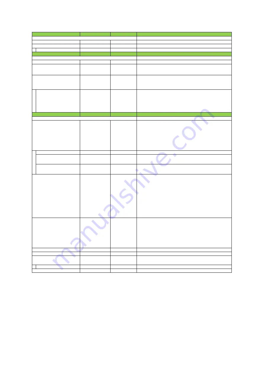
Setting range
Default value
Description
Configure LUT settings.
Red, Green, Blue
Red
Select the LUT channel to control.
0〜256
0
Set the LUT index table number.
LUTValue
0〜4095
Gamma≒1.0
Set the LUT value.
Setting range
Default value
Description
RGB, XYZ, HSI
RGB
Set the output image format.
Off, sRGB, AdobeRGB,
UserCustom
Off
Set the detailed mode when RGB is selected for the color space.
ー
RR
Select the ColorMatrix setting component.
[Setting range]
RR, RG, RB, GR, GG, GB, BR, BG, BB
ColorMatrixValue
-2.0 〜 2.0
ー
Set the Color Matrix value.
[Default value]
ColorMatrixValue [RR] = 1.0, ColorMatrixValue [RG] = 0, ColorMatrixValue [RB] = 0
ColorMatrixValue [GR] = 0, ColorMatrixValue [GG] = 1.0, ColorMatrixValue [GB] = 0
ColorMatrixValue [BR] = 0, ColorMatrixValue [BG] = 0, ColorMatrixValue [BB] = 1.0
Setting range
Default value
Description
Configure settings for digital input/output.
Line1 (TTL Out 1),
Line4 (TTL In 1),
Line5 (Opt In 1),
Line8 (TTL Out 2),
Line9 (TTL Out 3),
Line10 (TTL In 2),
Line12 (TTL Out 4),
Line13 (TTL In 3)
ー
Select the input/output to configure.
Line Mode
Input, Output
ー
Display the input/output status
(whether it is input or output)
.
Line Inverter
True, False
False
Enable/disable polarity inversion for the selected input signal or output
signal.
Line Status
True, False
ー
Display the status of the input signal or output signal
(True: High, False: Low)
.
ー
ー
Display the input/output signal status. The state is shown with 16 bits. Bit
assignments are as follows.
bit0:Line1
bit3:Line4
bit4:Line5
bit7:Line8
bit8:Line9
bit9:Line10
bit11:Line12
bit12:Line13
bit1, bit2, bit5, bit6, bit10, bit13-31 unused (fixed 0)
ー
ー
Select the line source signal for the item selected in [Line Selector].
[Setting range]
Acquisition Active, Frame Active, Exposure Active,
LVAL, Pulse Generator 0, Pulse Generator 1, Pulse Generator 2, Pulse Generator 3,
User Output 0, User Output 1, User Output 2, User Output 3,
Line4 (TTL In 1), Line5 (Opt IN 1), Line10 (TTL In 2), Line13 (TTL In 3),
Logic Block 0, Logic Block 1, Encoder Trigger, Encoder Direction
TTL, OptoCoupled
ー
Display the signal format.
0 〜 1000000 step 100
Off
Remove noise from the OptIn input signal of Digital I/O.
UserOutput0, UserOutput1,
UserOutput2, UserOutput3
UserOutput0
Set the UserOutput signal.
UserOutputValue
True, False
False
Set the value for the UserOutput selected in [UserOutputSelector].
Red, Green, Blue
Red
Select the channel for exposure active.
LUTSelector
Color Transformation Mode
e) LUTControl
f) Color Transformation Control
LUTIndex
ColorMatrixValueSelector
Color Transofrmation RGB Mode
Line Source
Line Format
Line Selector
g) Digital I/O control
Item
UserOutputSelector
Item
OptInFilterSelector (ns)
LineStatusAll
Item
ExposureActiveSource
SW-4000TL-10GE
—
4
7
—
Summary of Contents for SW-4000TL-10GE
Page 58: ...SW 4000TL 10GE 58 Spectral Response Wave length nm Relative Response ...
Page 59: ...SW 4000TL 10GE 59 Dimensions F mount SW 4000TL 10GE F Dimenstional tolerance 0 3mm Unit mm ...
Page 60: ...SW 4000TL 10GE 60 M42 mount SW 4000TL 10GE M42 Dimenstional tolerance 0 3mm Unit mm ...
Page 64: ...SW 4000TL 10GE 64 Revision Date Changes Revision history 1 0 Apr 2019 First version ...


