― 36 ―
LED Lights
– I/O Board
The I/O Board has 4 LEDs to indicate the status of the heaters, power supply, and microcontroller
(I/O Board setup parameters). The locations of these LEDs are shown in Appendix A. An explanation
is shown in the table below. Note: Green + Red combination may appear as Orange.
#
Function
Color/Status
1
Camera heater status
Green
– heater enabled by microcontroller but no current is running
Red
– heater current is running but heater is not enabled
Green
+
Red
– heater is enabled and current is running (Normal state)
2
Microcontroller status
Green
– I/O Board setup parameters are all OK (Normal state)
Red
– At least one I/O Board parameter is not OK
(Possible errors are demist heater, camera heater, and/or LED
Ring Light boards)
3
Power indicator
Green
– 24V input voltage present. 12V regulated voltage not present.
Red
– 12V regulated voltage present. 24V input voltage not present.
(Note: this voltage can be powered down from the microcontroller
if temperature gets too high or too low)
Green
+
Red
– 24V input and 12V regulated voltages present (Normal
state)
4
Demist heater status
Green
– heater enabled by microcontroller but no current is running
Red
– heater current is running but heater is not enabled
Green
+
Red
– heater is enabled and current is running (Normal state)
Table 4
LED status lights
Accessing Log File
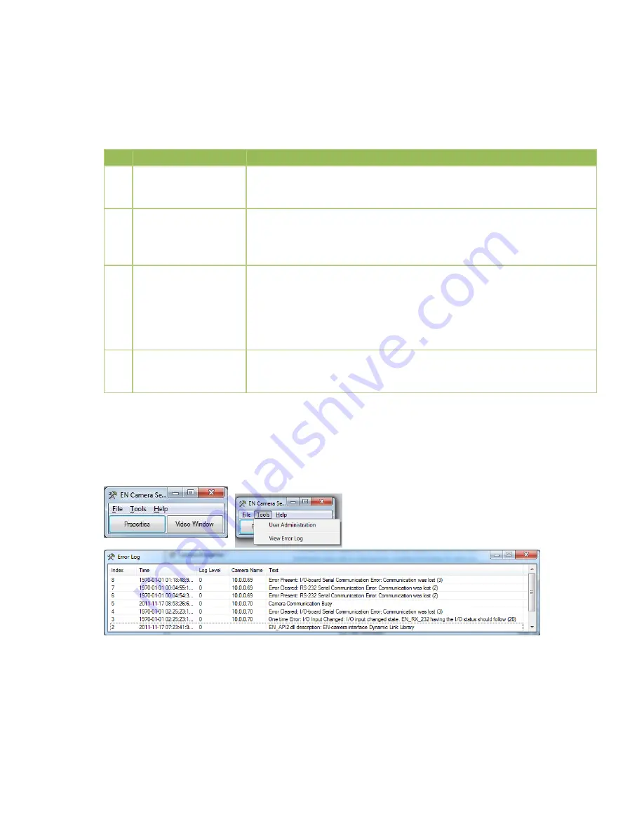
The log file can be found in the EN Setup start window, under Tools, and View Error Log.
You can also right click on that window and access the historical log file stored on your computer.


