― 25 ―
vehicle leaves the detection area. In “Front Shot” mode the vehicles will be travelling towards the
camera and the triggers are then generated when vehicles enter the detection area.
Detection Grid
– It is possible to enable/disable the Vehicle Detection in each of the 9 grids of the
detection area. It is recommended to disable the middle (Grid 5) in dual-lane configuration. This will
minimize the number of multi-triggers that might occur if the passing vehicles get too close to the
middle detection zone (which is shared between both left and right lane).
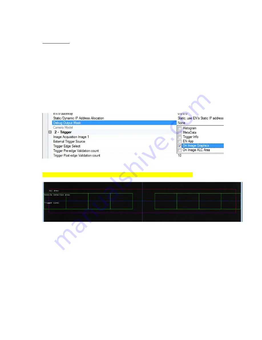
Visualization helper for Vehicle Detector and ALC setup
The camera can superimpose the Vehicle Detection Area and Auto Level Control (ALC) Area onto the
image to help during trigger line setup. To enable visualization enable them in “Debug Output Mask”:
*
Select
“
On Image Graphics
” (Vehicle Detector): to show Vehicle Detection Area
Select
“
On Image ALC Area
”: to show ALC Area
Figure 23. Vehicle Detector and ALC visualization settings
* Be sure to disable the graphics when finished. They appear in the final image!
Figure 24. The on-image visualization helper as displayed in the image
The visualization elements consist of:
Vehicle Detection Area (green boxes):
Each box represents 1 detection grid. There are 2 groups: left lane and right lane.
Trigger Line: when in “Live” view mode, aim the camera so that the plates for each lane are
at this Trigger Line and in their respective side.
A trigger happens as a vehicle drives past the Trigger Line and comes out of the detection
area.
The middle blue vertical line should be on top of and line up with the center of the lane (single
lane configuration) or with the lane divider (dual lane configuration).
Auto Level Control (ALC) Area (red & purple box):
The ALC area should be configured as close to the license plate area as possible to ensure
accurate reading of the current lighting conditions.


