background image


― 21 ―


The LED Ring Light illuminator has two usage modes: Traffic Safety and Triggered Flash Mode.  

Traffic Safety (Continuous Light):  

Traffic Safety mode is designed to minimize the level of driver distraction caused by periodic flashes 
emanating from the LED Ring Light. In this mode, the LED Ring Light is constantly on at a low level of 
brightness specified by the user in the LED Ring Light Settings window.  When a passing vehicle 
triggers the camera system, the Drive5 will produce a high intensity flash sufficient for color image 
capture. But because of the continuous lighting, the flash will be much less noticeable to the 

driver’s 

already partially adjusted eyes. To enable Traffic Safety mode and set a continuous light intensity 
level, right click on the camera symbol in the Properties window and select Advanced Settings 

–> 

Configure LED Ring-Light Settings. 

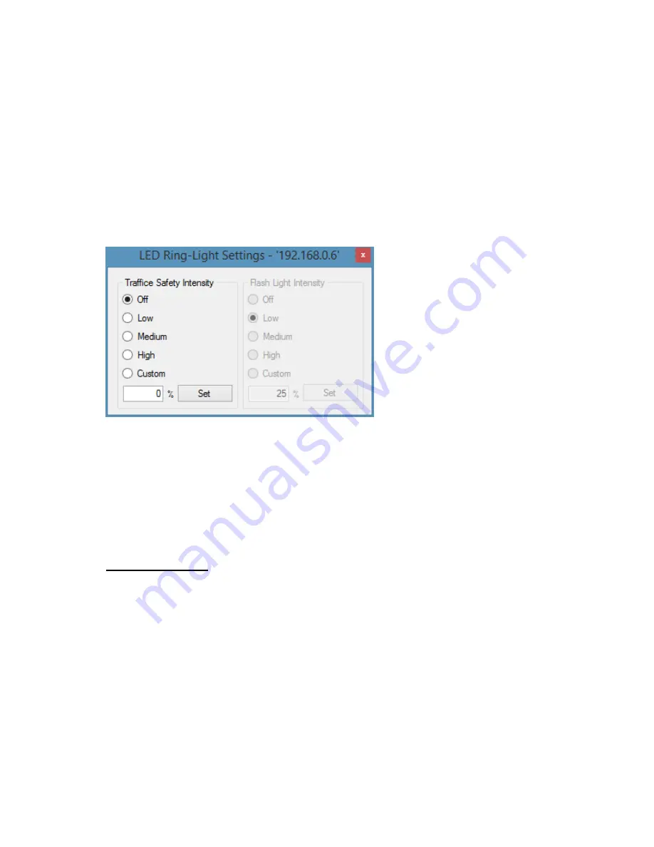
A dialog box will open and the settings for the LED Ring Light can be controlled from here: 


Figure 18.  LED Ring Light Settings dialog box 

When selecting light intensity settings, those settings are automatically saved in the I/O Board and 
become the default settings next time the system is powered on.  When selecting a “custom” setting, 
the [Set] button must be selected for the value to take effect. 

Triggered Flash: 

When the camera captures an image, the LED Ring Light can flash at a different light level.  The LED 
Ring-Light Mode and LED Ring-Light Intensity settings affect this usage. 

LED Ring-Light Mode - There are two options available (see Figure 19). 

Summary of Contents for Drive5

Page 1: ...Installation Manual Quick Start Guide Document P N 10895 Document Version B 2015 JAI Drive5 HIGH PERFORMANCE CAMERA SYSTEM FOR ANPR APPLICATIONS ...

Page 2: ... trademarks of Microsoft Corporation in the United States and or other countries Warranty Each JAI product is warranted to be free from defects in material and workmanship under normal intended use and service if installed in accordance with this manual The standard warranty period for the Drive5 is 1 year 12 months and begins on the date of shipment from JAI stock This warranty shall not apply to...

Page 3: ...een tested and found to comply with the limits for a Class A digital device pursuant to Part 15 of the FCC Rules These limits are designed to provide reasonable protection against harmful interference when the equipment is operated in a commercial environment This equipment generates uses and can radiate radio frequency energy and if not installed and used in accordance with the instruction manual...

Page 4: ...setup 17 4 1 Pre alignment checklist 18 4 2 Select a suitable vehicle license plate and plate stand for the setup 19 4 3 Connect the setup computer to the camera 19 4 4 Drive and park the setup vehicle correctly 20 4 5 Perform initial lens adjustment and camera aiming 20 4 6 LED Ring Light embedded illuminator setup 20 4 7 Automatic triggering and light sensing configuration 23 4 8 High dynamic ra...

Page 5: ...table below Drive5 X4 connector pin number Wire color Signal 1 White orange in Cat5e cable Ethernet A 2 Orange in Cat5e cable Ethernet A 3 White green in Cat5e cable Ethernet B 4 Green in Cat5e cable Ethernet B 5 White blue in Cat5e cable Ethernet C 6 Blue in Cat5e cable Ethernet C 7 White brown in Cat5e cable Ethernet D 8 Brown in Cat5e cable Ethernet D 9 Black wire GND 10 Red wire 24V dc 11 Grey...

Page 6: ...roubleshooting information e Configure your network adapter for a static IP of 10 0 0 xx with xx being anything but 65 This will put the computer on the same subnet as the camera as configured at the factory the camera is set to 10 0 0 65 See Figure 16 for an example f Start EN Setup on laptop Wait approximately 1 minute for the camera to boot up g Click on the Video button then on the camera in t...

Page 7: ... click on the image and select Preview Image to get a view of the entire image l Readjust the pan tilt roll zoom and focus until satisfied with the field of view and focus Figure 4 Properly adjusted image dual lane setup m Tighten lens adjustment thumbscrews n Lock down the pan tilt and roll adjustments o Remove Ethernet cable from the camera RJ45 and reinstall the cable from the I O Board RJ45 in...

Page 8: ... O Board and a pan tilt roll mounting bracket The Drive5 features an embedded JAI trigger light sensor for image triggering and image contrast control It also features an embedded LED Ring Light illuminator infrared white or blue for independent 24 7 operation and excellent license plate contrast see Figure 6 The Drive5 system is Ethernet based with a built in processor using an embedded Linux O S...

Page 9: ... 9 Figure 6 Drive5 system with I O Board and LED Ring Light I O Board LED Ring Light ...

Page 10: ...on Figure 9 depicts a typical side fire configuration 2 4 Overhead positioning Over lane camera mounting is always employed when the road width being monitored contains three or more lanes of traffic when a convenient overhead structure is already in place or when preventing vandalism is a paramount concern Each Drive5 system can be configured to cover a single lane or two lanes depending on type ...

Page 11: ... tilt considerations The requirement to freeze the motion of high speed vehicles limits how steep or shallow the tilt angle of the camera may be For example it is important to prevent the horizon from appearing in the image and thereby allowing the sun to blind the camera For over lane installations a camera tilt between 20 to 30 is recommended with 25 being considered the optimal angle This angle...

Page 12: ...nal TNL 50 external flash unit By positioning this high powered flash unit a short distance away from the Drive5 proper exposure of the overall scene can be achieved without overexposing the plate Table 1 below shows the minimum distance from Drive5 to flash light unit distance normal from camera license plate axis Drive 5 Unit to Flash Spacing minimum Approximate distance in feet 3 25 Approximate...

Page 13: ...e spacing between flash and camera will have to be increased to avoid increasing the retro reflectivity effect and the intensity of the flash will have to be increased or else the background will not be visible in the image even when retro reflective license plates are close to saturation ...

Page 14: ...rect connection of a single unit to a 24V DC power supply inrush current is 3 5 A steady state current is 2 0 A System Components Current Steady State Current Inrush Drive5 System 0 with heater on 2 0 A 3 5 A Drive5 System 1 with heater on 2 0 A 3 5 A J Panel VJP 300 0 2 A 1 5 A Total 4 2 A 6 5 A When connected using J Panel inrush current is limited to 6 5 A Table 2 Drive5 power requirements 3 2 ...

Page 15: ...tationary with a 24 mm wrench Using a second 24 mm wrench tighten the sealing nut until the cable is securely held in place Torque to approximately 35 in lbs 3 9 Nm Note there is no standard SAE wrench size that will properly fit the hex nuts You must use either a 24 mm metric wrench or an adjustable wrench Step 6 Move the thin wire 2 inches 5 cm away from the cable end and fold the braid back ove...

Page 16: ... 16 Figure 14 Drive5 system cable Figure 15 Wires are inserted in Drive5 I O Board X4 connector ...

Page 17: ...Output Mask in Section 1 of the EN Setup camera properties and selecting On Image Graphics as shown below This region shows the area where the camera will detect a moving vehicle This will give the approximate trigger line Since the unit is using motion detection technology the trigger line will vary a little depending on the speed of the vehicle If the installation utilizes other modes for trigge...

Page 18: ...needs to have an Ethernet network adapter installed preferably 1 Gigabit Ethernet Adapter and the TCP IP network configured with the correct IP address subnet mask and default gateway The setup computer and the cameras need to be on the same subnet The cameras are shipped with the standard IP address 10 0 0 65 and subnet address 255 255 255 0 and the setup computer needs to be assigned an IP addre...

Page 19: ...iew of the road Connect the setup computer s network adapter directly to the camera Configure your network adapter for a static IP of 10 0 0 xx with xx being anything but 65 This will put the computer on the same subnet as the camera as configured at the factory the camera is set to 10 0 0 65 Figure 17 Example of direct connection to the camera Once the setup computer is connected you can apply po...

Page 20: ...l adjustments on the mount aim the housing at the target vehicle Adjust the focus adjustment on the lens to achieve the field of view you desire 5 Right click on the image and select the Preview Image to get a view of the entire image Readjust the pan tilt roll and focus until satisfied with the field of view 6 Optional Use the measuring box to measure the size of the license plate Ensure it meets...

Page 21: ...justed eyes To enable Traffic Safety mode and set a continuous light intensity level right click on the camera symbol in the Properties window and select Advanced Settings Configure LED Ring Light Settings A dialog box will open and the settings for the LED Ring Light can be controlled from here Figure 18 LED Ring Light Settings dialog box When selecting light intensity settings those settings are...

Page 22: ... Intensity settings let you fine tune the light level for various ambient light conditions see Figure 20 Note additional settings in this camera properties section are for use with an external flash unit such as JAI s TNL 50 See the TNL 50 documentation for an explanation of the settings Figure 20 LED Ring Light flash mode and auto intensity settings in EN Setup When Auto Light Level is selected t...

Page 23: ...n setting up for automatic triggering Vehicle Detector trigger and light sensing ALC Vehicle Detector Trigger settings Select Vehicle Detector within External Trigger Source to enable the Vehicle Detector Trigger The system will automatically detect moving vehicles in up to two separate lanes Note that the traffic in both lanes must be moving in the same direction The Vehicle Detector uses a 200 l...

Page 24: ...tiple triggers occur within this time then only the first trigger will be accepted The purpose for this setting is to minimize the number of multi triggers where the same vehicle generates multiple triggers but only a single image is needed to identify the vehicle Lane Empty This setting is essential to the Rear Shot Lane Direction mode explained below This specifies the maximum number of empty fr...

Page 25: ...icle Detector to show Vehicle Detection Area Select On Image ALC Area to show ALC Area Figure 23 Vehicle Detector and ALC visualization settings Be sure to disable the graphics when finished They appear in the final image Figure 24 The on image visualization helper as displayed in the image The visualization elements consist of Vehicle Detection Area green boxes Each box represents 1 detection gri...

Page 26: ...tion on previous page ALC Target Value This is the set point for the closed loop control of the camera exposure This value represents the target average value for the ALC Region of Interest ROI It is a 10 bit value which is then four times higher than the average value measured in the output images from the Drive5 which are all in 8 bit resolution So if the ALC Target Value is set to 200 for insta...

Page 27: ...ging light scenarios are often caused by shadows being cast onto the scene in a way where the ALC measures the average of the road surface in shadow but where the vehicle will be in the direct sun and thereby inadvertently cause the vehicle to become over exposed However be aware that multi slope HDR reduces the contrast in the brighter parts of the image and also impacts the Drive5 s ability to p...

Page 28: ... knee point and the contrast of the bright part of the image will be lower when the HDR level is increased Another side effect is also that the images will get a pinkish tint so that the color fidelity of the brighter areas of the image will be lower Figure 27 above shows two settings Reset time at 70 85 of the exposure time This settings makes the sensor capable of coping with approximately twice...

Page 29: ...nt in order to make the parameters effective The following parameters need to be configured NTP Client Control Enable or Disable the NTP client in the camera NTP Server 1 2 3 IP address These parameters specify which NTP Server s on the network that the NTP Client will use for the time synchronization The first IP address in the list will be considered the preferred server NTP Max estimated Error ...

Page 30: ...igurable by the user NTP estimated error us This status value shows the estimated accuracy of the camera s time value relative to the UTC The estimate is based on the NTP protocol s ability to measure the communication latency and jitter and based on these measurements the NTP Client inside the camera can calculate the deviation from the NTP master to which it is connected The master does the same...

Page 31: ... AM PM Hour is from 01 to 12 24 hour time is displayed as Hour Minute Second Hour is from 00 to 23 12 hour ms time is displayed as Hour Minute Second Miliseconds AM PM 24 hour ms time is displayed as Hour Minute Second Miliseconds Streaming Enable Enable disable streaming NOTE use this link in VLC or other software to see the video streaming rtsp Camera IP 8557 PSIA Streaming channels 0 videoCodec...

Page 32: ... video output format selected and may look squeezed or stretched horizontally depending on the Source Height value To get a 1 to 1 pixel ratio use the minimum Source Height value for the Streaming Video Format selected 720 for 720p or 1080 for 1080p Set the starting pixel for the ROI by using Source Offset X and Source Offset Y 720p range 720 2048 1080p range 1080 2048 Source Offset X Range 0 to 2...

Page 33: ...wer ground Black Pin 10 Power 24V Red Pin 11 Vinit positive trigger input Grey Pin 12 Vinit negative trigger input Yellow LED Status Lights 1 Camera heater status 2 Microcontroller status I O Board setup 3 Power indicator 4 Demist heater status Connector X3 Trigger Device Input Pin 1 Ground Pin 2 Trigger pulse input Pin 3 Serial trigger command input Pin 4 RS 232 TTL serial transmit Pin 5 RS 232 T...

Page 34: ...ush Drive5 System 0 with heater on 2 0 A 3 5 A Drive5 System 1 with heater on 2 0 A 3 5 A J Panel VJP 300 0 2 A 1 5 A Total 4 2 A 6 5 A When connected using J Panel inrush current is limited to 6 5 A Table 3 Drive5 power requirements Source Type Communication to various external devices For TNL 50 use RS 485 For Laser use RS 232 Default is RS 485 Response Select between Normal and Interrupt Interr...

Page 35: ...ot set correctly in Camera Properties Check EN Setup camera properties section 2 for trigger properties Trigger External Trigger Source Check that the camera can be triggered via the EN Setup video window Eth Trigger Ethernet trigger must be enabled in properties section 2 Trigger External Trigger Source If system has a VJP 300 then activate trigger push button S1 and verify that an image is being...

Page 36: ...s not OK Possible errors are demist heater camera heater and or LED Ring Light boards 3 Power indicator Green 24V input voltage present 12V regulated voltage not present Red 12V regulated voltage present 24V input voltage not present Note this voltage can be powered down from the microcontroller if temperature gets too high or too low Green Red 24V input and 12V regulated voltages present Normal s...

Page 37: ...us Here possible errors for the camera can be found Fault Symptom Check Possible Reason Images showing artifacts Periodically clean window on housing Camera FW out of date See firmware update procedure in EN Camera Manual on JAI website www jai com Note since the Drive5 system contains no moving elements little maintenance is required ...

Page 38: ...ix C List of acronyms used ADR Automatic Dynamic Range ALC Auto Level Control FPS Frames Per Second HDR High Dynamic Range NTP Network Time Protocol OSD On Screen Display ROI Region of Interest VD Vehicle Detector ...

Page 39: ...www jai com Europe Middle East Africa Phone 45 4457 8888 Fax 45 4491 3252 Asia Pacific Phone 81 45 440 0154 Fax 81 45 440 0166 Americas Phone Toll Free 1 800 445 5444 Phone 1 408 383 0300 ...

Reviews: