background image

18

18


It is the responsibility of the installer to select mate-
rials based on their intended use, to carry out work 
properly,  to check the condition of the system that 
the unit will be connected to and that it ensures safe-
ty of use also concerning maintenance work and the 
possibility to examine the system. 

Q

The Jacuzzi® spas are class

 “1

” appliances and therefore they 

must be permanently connected, 

without any intermediate 

connections

, to the electrical system and to the protection sys-

tem (earth system).


The electrical system of the building must be provided 
with a 0.03A differential switch and with an efficient 
protection (earth) circuit.    


Check for proper operation of the differential switch 
by pressing the TEST button, which should trip.


Parts incorporating electrical components, except for 
remote control devices, must be located or fixed so 
that they cannot fall into the bath.   


Parts containing live parts must be inaccessible to a 
person in the bath.

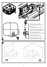
Q


For connection to the electrical mains, one or more all-pole circu-

it breaker(s) must be installed (depending on the installation type)  
(

 4

). It must be positioned in a place that complies with safety 

regulations and, in any case, which cannot be reached by those 
using the spa.

It is  mandatory to comply with this instruction. Any other 
procedure is prohibited.


If the building’s electrical system is not able to guaran-
tee a stabile power supply, it is recommended to install 
a voltage stabiliser that suitably dimensioned for the 
required power upstream of the equipment.

Q

The disconnection devices must be installed in the power 

supply network according to the installation instructions.

Q

The installation of electrical devices and equipment (sockets, 

switches, etc.) near the spa must be in compliance with legal 
standards and regulations in the country where the spa is in-
stalled.

Q

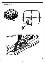
For the equipotential connection as required by specific nation-

al standards, the installer must use the terminal provided (stand-
ard 

EN 60335.2.60

) under the electronic box (

4

), and marked 

with the symbol  . In particular, an equipotential condition must 
be established for all metallic masses surrounding the spa, for ex-
ample water and gas pipes, metallic platforms, and so on.

Q

The appliance is equipped with an LED lighting system in 

compliance with Norm EN 62471:2009.

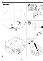
Positioning the spa

Q

  (


5

)  The spa can be set against a wall, as shown, 

leaving 

the three sides free relative to the electromechanical compo-
nents located under the spa, making sure that the spa can be 
inspected and the necessary maintenance can be performed.
  If you want to install the spa against multiple walls, a spa-
ce must be guaranteed for the removal of the panels and 
for any maintenance, and access must be guaranteed to the 
equipment in the tub compartment.


Prolonged sun exposure  could damage the material 
of which is made the spa shell, due to  its capacity to 
absorb heat (dark colours in particular). Don’t leave 
the spa to sun exposure  without adequate protection 
when not in use (cover thermal, gazebo, etc.).  


Any damage arising by not following these warnings 
are not covered by the guarantee.

Q

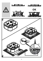
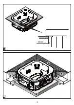
 The spa can be installed in various ways:

(


6

free 

standing on the floor or on a specifically prepared 

base.
 
- (


7

Semi-built in,

 so that only the base of the spa is built-in 

and therefore the side cover panels remain free. In this case, it is 
appropriate to prepare some removable under-frames (in ma-
rine plywood, etc.) that, besides aesthetically completing instal-
lation, allow the panels to be removed more easily. The size of 
the built-in space in the floor is obtained from that of the base 
of the spa (


1

).

NOTE: between the floor embedding and the panels, it is ad-
visable to leave enough manoeuvring space all around the 
spa in order to remove the panels (part A).

- (


8-9

built-in

, with the tub edge flush with the floor. 

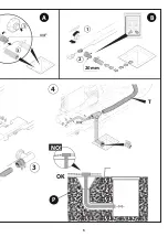
  (


9

)  In this case, a base support must be made under the 

bottom of the tub (in concrete and steel beams, (detail 1).  

Access to the hosing must be ensured and to all other electro-

mechanical parts that are under the tub, for example by making 
a passage along the outer perimeter, that is wide enough (about 
80 cm) to carry out all electrical and hydraulic connections and 
any maintenance operations (detail 2). This passage can be 
closed using removable under-frames (detail 3), with suitable 
supports (detail 4). 

Drainage for any water stagnation must also be provided (de-

tail 5).

Q

In any case, you will need to provide a support base that is 

suitable for the load of the spa as shown in the table of weights 
above.

Q

If the spa is installed indoors, remember that water evapora-

tion from the spa can cause very high levels of humidity, espe-
cially if temperatures are very high. Natural or forced ventilation 
helps to maintain personal comfort and reduce damage to the 
building due to humidity. 

Summary of Contents for Delos

Page 1: ...ructions for preinstallation KEEP CAREFULLY Fiche tecnique de pre installation CONSERVER AVEC SOIN Vorinstallationsblatt SORGF LTIG AUFBEWAHREN Ficha t cnica de preinstalaci n CONSERVAR CON CUIDADO De...

Page 2: ...x 179 8 8 62 80 190 215 R 54 204 x 179 8 8 64 80 Delos Delos pro Delos synthetic wood Delos pro synthetic wood Delos built in Delos pro built in 1 Q Italiano 12 Q English 16 Q Fran ais 20 Q Deutsch 2...

Page 3: ...3 2...

Page 4: ...4 2 1 2 A B A B A B P 1 2 A B 19 cm 30 cm A B 18 cm 81 cm 3 Delos...

Page 5: ...5 4 A B 3 4 1 3 OK P NO 3 4 T 20 mm 1 2 3...

Page 6: ...6 18 cm 81 cm A B 19 cm 30 cm 2 1 2 A B A B A B A B P 1 2 3a Delos pro...

Page 7: ...7 20 mm 1 2 3 4 3 4 A B 3 4 1 3 OK P NO...

Page 8: ...massimo dell impianto size based on table Maximum absorption of the system dimensionner en se rapportant au tableau Absorption maximale de l installation auf der Grundlage der Tabelle maximale Aufnah...

Page 9: ...9 12 cm A A A A A 7 6 OK...

Page 10: ...10 20 mm 2 2 4 4 5 5 1 3 3 8 9...

Page 11: ...11 10 52 5 cm 78 cm C 57 5 cm 3 4 C IN OUT Delos pro...

Page 12: ...area d appoggio carico concentrato su area d appoggio m2 kg m2 3 57 459 Sicurezza d uso Q L impianto se installato da personale qualificato rispettando le disposizioni riportate nel manuale d installa...

Page 13: ...nche il collegamneto del circuito primario con l impianto che fornir l acqua calda nonch il collegamento del la cassetta elettrica vedi schema elettrico manuale d installazio ne con i dispositivi che...

Page 14: ...le speci fiche norme nazionali l installatore dovr usare il morsetto pre disposto norme EN 60335 2 60 4 e contraddistinto dal simbolo In particolare dovr essere realizzata l equipoten zialit di tutte...

Page 15: ...orre tener presente che l evaporazione dell acqua della spa soprattutto con temperature elevate pu generare livelli di umidit molto alti La ventilazione naturale o forzata contribuisce a mantenere il...

Page 16: ...verage volume of use water volume MAX Total max weight kg litres litres kg 250 860 1390 1640 support area concentrated load on support area m2 kg m2 3 57 459 User safety Q If installed by qualified pe...

Page 17: ...hat control the recirculation of the hot water in the exchanger s pri mary circuit For this purpose normally there is an open contact in the electrical box 5A MAX see the wiring diagram installa tion...

Page 18: ...71 2009 Positioning the spa Q 5 The spa can be set against a wall as shown leaving the three sides free relative to the electromechanical compo nents located under the spa making sure that the spa can...

Page 19: ...any damage caused by excessive humidity or by overflowing water Consult a specialist for indoor installation Q Concerning suitability of the electrical system and of connec tions refer to the install...

Page 20: ...AX poids total max kg litres litres kg 250 860 1390 1640 surface d appui charge concentr e sur surface d appui m2 kg m2 3 57 459 S curit d utilisation Q L installation si elle est effectu e par un tec...

Page 21: ...nt le raccordement du circuit primaire l in stallation qui fournira l eau chaude et le raccordement du bo tier lectrique voir sch ma lectrique manuel d installation aux di spositifs de commande de rec...

Page 22: ...rises in terrupteurs etc proximit du spa doit respecter les normes et dispositions l gales applicables dans le pays o le spa est install Q Pour le raccordement quipotentiel pr vu par les normes na tio...

Page 23: ...re de r aliser une base de soutien en mesure de supporter la charge du spa en tenant compte du tableau Poids voir plus haut Q En cas d installation l int rieur il est n cessaire de tenir compte du fai...

Page 24: ...hes VolumenVerbrauch Wassermenge MAX max Gesamtgewicht kg liter liter kg 250 860 1390 1640 Auflagebereich Konzentrierte Belastung im beanspruchten Bereich m2 kg m2 3 57 459 Betriebssicherheit QWenndie...

Page 25: ...rmetauscher versorgen m s sen einen ausreichenden Abstand vom Stromkabel haben Q Daneben auch den Prim rkreis mit der Hei wasseranlage ver binden den Schaltkasten siehe Elektro Schaltplan Installation...

Page 26: ...ionsland geltenden gesetzlichen Vor schriften zu erfolgen Q F r die von den einschl gigen nationalen Richtlinien vorge sehene Erdung hat der Installateur die hierf r unter dem elek tronischen Schalkas...

Page 27: ...chender Untergrund vorbereitet werden hierzu die oben ab gef hrte Tabelle Gewichte konsultieren Q Wird in einem Innenraum installiert ist darauf zu achten dass die Wasserverdampfung des Spa Pools haup...

Page 28: ...litros litros kg 250 860 1390 1640 rea de apoyo carga concentrada sobre rea de apoyo m2 kg m2 3 57 459 Seguridad durante su utilizaci n QElequipo sihasidoinstaladoporpersonalcualificadoconforme a las...

Page 29: ...imario con la instala ci n que suministrar el agua caliente as como la conexi n de la caja el ctrica vea el esquema el ctrico en el manual de instalaci n con los dispositivos que controlar n la recirc...

Page 30: ...minipiscina Q Para la conexi n equipotencial prevista por las normas nacionales espec ficas el instalador deber utilizar el borne previsto normas EN 60335 2 60 bajo la caja el ctrica 4 y marcado con e...

Page 31: ...na teniendo en cuenta el cuadro Pesos ofrecido arriba Q En caso de instalaci n en interiores es necesario tener en cuenta que la evaporaci n del agua de la minipiscina sobre todo con altas temperatura...

Page 32: ...60 16 k 3 5 j DELOS PRO DELOS PRO SOUND x Blower Pro Sound Pro Sound Spa Pak 220 240 50 60 23 k 5 15 j 0 6 j 0 25 j 2 5 k 0 5 j x Blower Pro Sound Pro Sound Spa Pak 220 240 50 60 8 8 k 1 95 j 0 6 j 0...

Page 33: ...3a Q A A B spa 1 2 3 4 Q 10 Q 5A Q DELOS 220 240 1 380 415 2N DELOS PRO 220 240 1 380 415 2N 380 415 3N Q 220 240 Q 220 240 Q H 05 VV F 220 240 V min 4 mm2 380 415 V min 2 5 mm2 Q Performance spa pak...

Page 34: ...34 34 spa Spa Jacuzzi EN 60335 2 60 EN 61000 EN 55014 Q Q Spa Jacuzzi 1 0 03 A TE T Q 4 spa Q Q spa spa Q EN 60335 2 60 4 Q EN 62471 2009 Q 5 spa spa Spa 6 7 spa spa 1...

Page 35: ...8 9 9 1 80 c 2 3 4 5 Q spa Q spa JacuzziEurope...

Page 36: ...cio Unico Direzione e Coordinamento Jacuzzi Brands Corp USA S S Pontebbana km 97 200 33098 Valvasone PN ITALIA Tel 39 0434 859111 Fax 39 0434 85278 www jacuzzi eu info jacuzzi it Jacuzzi Spa Bath Ltd...

Reviews: