9
INSTALLATION
Alexa Electrical Conversion
The Alexa spa, may be converted from the factory supplied 115 VAC, 20 AMP to operate on a 230 VAC, 50
AMP circuit. This must be a protected electrical service with copper conductors, a 4-wire grounded type GFCI
protected circuit and have no other appliances on the circuit. If you do not have this kind of circuit, a qualified
electrician should be called in to install the necessary wiring. Inadequately sized wiring may cause a malfunction
and bring about permanent damage to the spa’s electrical system. The circuit must also have a ground wire in order
to take advantage of the designed-in safety features of the spa. A bond wire must also be used.
CAUTION: Without proper grounding and bonding, a system malfunction may cause fatal shock.
This conversion will increase the heating capability of your spa's heater and convert the output from 1.25kW to
5.5 kW (21 AMP). We recommend that this rewiring be done by a qualified electrician. A wiring diagram is provided
on the inside cover of the electrical control box. When this conversion to 230 VAC has been made, any combination
of operating modes is possible, including having the heater on when the whirlpool mode is activated. Also, the heat-
up rate will be approximately four times greater.
To convert to 230 VAC, 50 AMP operation:
1. Turn OFF 20 AMP breaker at main electrical panel.
2. Open the skirt door access panel.
3. Loosen and remove 4 screws securing the electrical cabinet cover and set them aside.
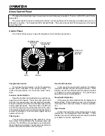
4. Loosen screws at bottom side of terminal block and remove power cord cable clamp. Remove and discard GFCI
power cord.
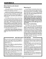
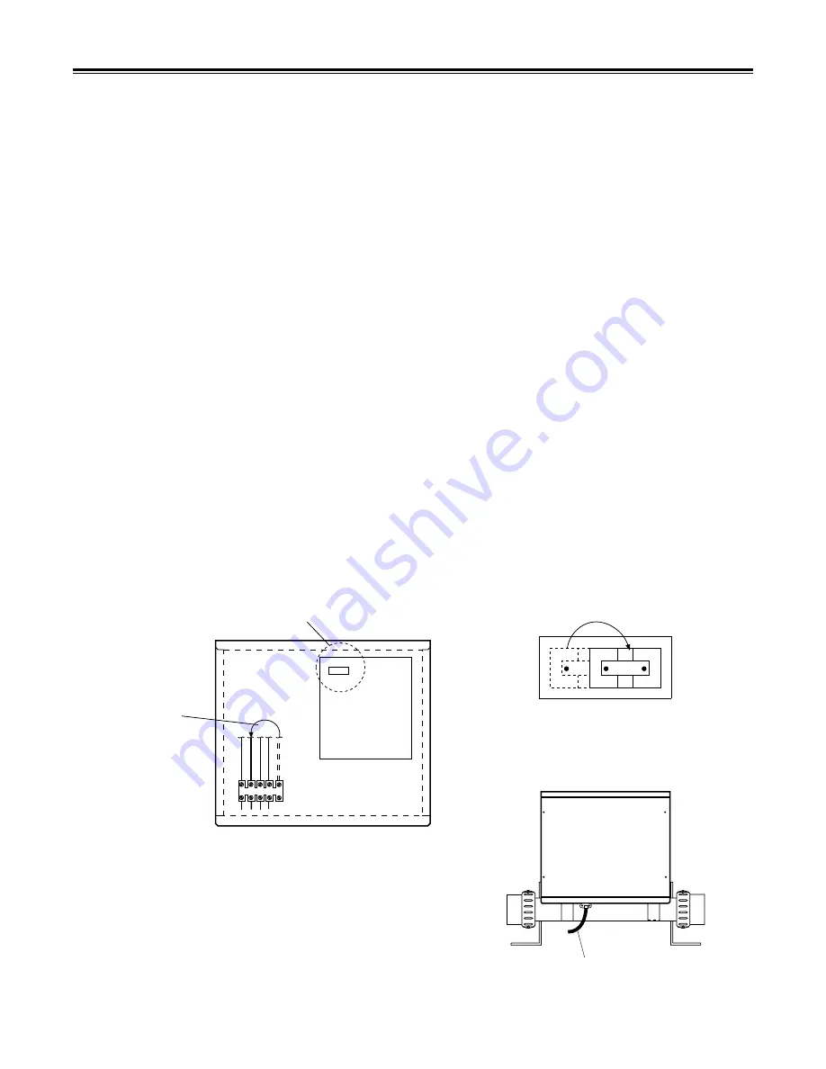
5. Install 230 VAC 4-wire power cord in accordance with local code requirements. Insert the wires into the bottom
side of the terminal block and tighten the screws. Refer to Figure 1.
6. Loosen the screw on the top side of the terminal block. Move the red wire from position 1 to position 4. Tighten
the screw. Refer to Figure 1.
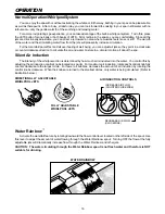
7. Move the jumper at circuit board location J8 from 20A position to 50A position. Refer to Figures 1 and 2.
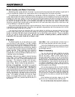
8. Replace electrical cabinet cover and tighten screws. Refer to Figure 3.
9. Make sure spa is filled with water to proper level. Turn ON 50 AMP GFCI breaker at the main electrical panel.
10. Test GFCI for proper operation.
BLACK
WHITE
RED
1
2
3
4
5
SEE FIGURE 2
LOOSEN SCREW.
MOVE THE RED WIRE
FROM TERMINAL 1
TO TERMINAL 4.
TIGHTEN SCREW.
FIGURE 1
GREEN
50A
20A J8
CIRCUIT
BOARD
20A
50A
J8
FIGURE 2
FIGURE 3
230 VAC 4-WIRE
POWER CORD


