GB-NL-F-28
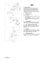
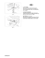
Fig.18
Fig.19
Fig.20
GB
ASSEMBLY OF CUTTING
UNITS AND MACHINE SET-
UP
CUTTER DECK SET-UP
1.
Uncrate the five cutterdecks. There are two
types of cutterdecks: Three with movable
caster wheels for the front of the tractor and
two with fixed caster wheels for the sides of
the tractor.
2.
Start the tractor and lower the lift arms fully.
Stop the tractor.
3.
All cutterdecks are attached in the same way,
as follows:
a.
Remove the six bolts A from the top of
the cutterdeck.
b.
Mount the hydraulic motor onto the
deck using the six bolts removed.
Position with the centre hose (drain
hose) at the rear of the deck. Tighten
the bolts securely.
4.
Move pivot shaft.
a.
Remove bolt B and two washers
securing the pivot shaft to the tractor
arm, noting the order of assembly.
b.
Remove the pivot shaft from the tractor
arm.
c.
Remove collar C from the pivot shaft.
d.
Install the pivot shaft in the deck as
shown. Replace collar C on the pivot
arm and secure with bolt and nut.
Summary of Contents for AR250 TURBO
Page 2: ...2001 Textron Inc All Rights Reserved...
Page 4: ......
Page 6: ......
Page 8: ...GB NL F 2 Fig 1 Product Name Date Weight Power Serial Number...
Page 45: ...GB NL F 39...
Page 68: ...GB NL F 62 Fig 42...
Page 70: ...GB NL F 64 Fig 42...
Page 72: ...GB NL F 66 Fig 42...
Page 74: ...GB NL F 68 A903491 A903489 A903492 A903488 A903496 A903493 A903490 A911410 A911409 A911416 15...
Page 76: ...GB NL F 70...
Page 82: ...I D 2 Fig 1 Product Name Date Weight Power Serial Number...
Page 116: ...I D 36...
Page 119: ...I D 39...
Page 120: ...I D 40 Lubricate at arrows...
Page 142: ...I D 62 Fig 42...
Page 144: ...I D 64 Fig 42...
Page 146: ...I D 66 A903491 A903489 A903492 A903488 A903496 A903493 A903490 A911410 A911409 A911416 15...
Page 148: ...I D 68...
Page 152: ......
Page 153: ......

