ProPuls 320C
Operating manual
Page 57
21. Maintenance, coolant JPP and safety check
Disconnect mains prior to any service and maintenance work!
The welding unit is, on principle, maintenance-free. However, make it a rule to carry out the following work:
Clean current contact tip and gas nozzle regularly, removing welding spatter and other impurities. Add Anti-Stick
agent on nozzles after cleaning to reduce undesirable spatter adhesion.
Check current contact tip regularly for wear or damage, replace in time.
Clean the welding unit by air-blasting from inside according to pollution level. In order to guarantee a permanent
good cooling effect pay attention to the cooling ribs of the water cooler: they should not be covered by dust.
- ONLY use JÄCKLE coolant JPP (Order No. 900.020.400)
- Unsuitable coolants can cause property damage and loss of warranty.
- Do not mix with water or other coolant.
- Do not weld without cooling water! Tank must always be full.
- Pump must not run dry, not even for a short time. Deaerating the pump.
- Hazardous to health – keep away from children!
MATERIAL SAFETY DATA on
www.jaeckle-sst.de
available.
- Frost-resistance up to -30°C
Attention:
This Welding unit has to be safety checked every year by JÄCKLE Company or another special qualified
electrician according to the harmonized standard
IEC 60974 – 4
Safety, maintenance and inspection of arc welding equipment in use
22. Option Potentiometer remote control and Push-pull torch
Option Potentiometer remote control:
It is possible to connect two potentiometers as remote control with this equipment.
With the potentiometer 1 the welding power, and with the potentiometer 2 the arc length can be regulated.
If the potentiometer is connected, the regulation in the control box and the up / down function in the torch is
automatically deactivated.
The cables are not connected to the 7-pin socket in the wire feeder.
If necessary, the cables must be connected to a further socket.
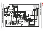
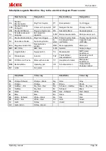
The wiring is described in chapter 26 – Circuit diagrams, page 72.
Ground
gray wire, +10 VDC
light blue wire, potentiometer 1
green wire, potentiometer 2
blue wire
ATTENTION
: As shown in the circuit diagram, there must be mandatory installed a protection diode in the
ground wire!
Option Push-Pull Torch:
ATTENTION:
it may only be connected a push-pull system for 24V DC!
42V or 48V systems are not permitted and lead to damage!
The cables are not connected to the 7-pin socket in the wire feeder.
If necessary, the cables must be connected to a further socket.
The wiring is described in chapter 26 – Circuit diagrams, page 72.
+24V DC (Push-Pull)
white wire, Ground
black wire
Summary of Contents for ProPuls 320 Compact
Page 2: ......
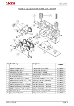
Page 66: ...ProPuls 320C Operating manual Page 62 25 Ersatzteile spare parts Frontansicht front view...
Page 68: ...ProPuls 320C Operating manual Page 64 Seitenansichten side view...
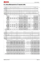
Page 73: ...ProPuls 320C Operating manual Page 69 27 Schwei programme Program table...
Page 74: ...ProPuls 320C Operating manual Page 70...
Page 75: ......


