ITW Dynatec
Chapter 5
Maintenance and Repair Notes
Page 44
UFD Applicator, Manual 40-43, Rev. 6.16
Testing Resistance of the RTD Temperature Sensor
(Options D, M, N and P in Chapter Model Designation Guide)
WARNING
Heed all security advices given in Chapter 5.1.
Maintenance and repair work is only permitted for skilled personnel!
1. Stop all motors.
2. Turn the ASU OFF or disable the Applicator and preheater zones at the control panel.
Disconnect all electrical cables from the Applicator.
3. Relieve the adhesive pressure by following the instructions under Chapter 5.4
“Relieving Adhesive Pressure”.
4. Unplug the electrical cable from the adhesive supply hose or extension cable to
expose the pins in the cable.
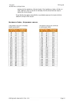
Note: The resistance value (Ohms) of the temperature sensor depends on the
temperature of the sensor at the time it is being tested. All values listed in the table
below are given at 25°C (77°F). To correct for ambient temperatures other than 25°C
(77°F), see next Chapter “Resistance Tables, Temperature sensors” for complete
resistance-temperature tables for the RTD sensors.
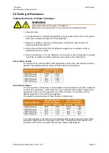
5. Using the schematics in Chapter 9 as a reference, measure the resistance of the
sensor and compare to the values in the table below. A tolerance of ± 5% is allowed
for ambient temperature differences. A sensor that tests outside of this range must be
replaced.
Applicator Control
Sensor Resistance
at 25°C (77°F)
DynaControl (option D)
110 ohms
MCV Control (option M)
110 ohms
Upgrade (Ni, option N)
138 ohms
Allen-Bradley (option D)
110 ohms
Upgrade (Pt, option P)
110 ohms
Testing the J-type Thermocouple Temperature Sensor
(Control option L in Chapter Model Designation Guide)
WARNING
Heed all security advices given in Chapter 5.1.
Maintenance and repair work is only permitted for skilled personnel!
1. Stop all motors.
2. Turn the ASU OFF or disable the Applicator and preheater zones at the control panel.
Disconnect all electrical cables from the Applicator.
3. Relieve the adhesive pressure by following the instructions under Chapter 5.4
“Relieving Adhesive Pressure”.
4. Unplug the electrical cable from the adhesive supply hose or extension cable to
expose the pins in the cable.
5. Using the schematics in Chapter 9 as a reference, first measure the resistance across
the thermocouple leads to check for an open junction. The resistance should be zero


