Chapter 4
Installation & Startup
ITW Dynatec
UFD Applicator, Manual 40-43, Rev. 6.16
Page 25
Chapter 4
Installation & Startup
CAUTION
•
Before setting up, please read this documentation carefully.
•
Pay attention to all the installation and connecting advices.
•
Heed all safety instructions mentioned in Chapter 2.
4.1 Conditions for set-up and mounting
Place requirement
Install the Applicator in the machine so that the operator is able to work on it from all
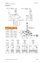
sides, for e.g. for adjusting, preparing, maintaining, repairing, cleaning, etc. See drawing
of the unit for admeasurements.
Mounting and alignment
•
The complete unit has to be set up on solid, stable and flat ground.
•
The alignment in height of the complete system has to be considered.
•
The alignment of the machine has to be considered.
Electrical connection
•
Necessary electrical connection has to be provided. See electrical schematics.
•
Never connect or disconnect plug-and-socket connections under load!
•
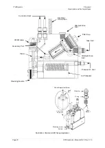
The service block’s incoming electrical power and temperature control is supplied
through the flexible cable exiting the adhesive supply hose cuff or through an
extension cable from the ASU. The Applicator has a circular, plastic connector which
mates with the connector attached to this cable.
•
Incoming power and temperature control for the air preheater, if applicable, is supplied
by a cable extension from the ASU.
Pneumatic connection
•
In any case the air has to be clean and dry! See advice in Chapter 4.3 “Quality of
compressed air”.
•
Please heed that units with high air demand may not be used at the same time with
the same air supply.
•
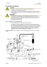
Incoming module-activation air is supplied through a solenoid valve. It must be clean
and unlubricated.
For conventional modules
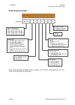
(module option H, V, HQ or VQ in the model number (see
previous pages), the module activation air is controlled by a four-way solenoid valve
and should be separately regulated and maintained at a pressure between 4.1 to 6.9
bar (60 to 100 psi). Air lines from the solenoid valve should be 6.4mm (1/4 inch).
Head air inlet ports are G 1/8 threads (1/8 NPT).
For snuffback modules
(all other module options), the module activation air is
controlled by a either a four-way or a five-way solenoid valve. See Appendix A and B
for details on the solenoid setup.
•
Incoming process (preheater) air must be supplied through a pressure regulator. The
air must be clean and unlubricated. Operating pressure depends on the choice of
nozzle. The Applicator’s air supply line must be at least 1/4” O.D. For the UFD 150
applicator, 3/8” O.D. airline is recommended.
Advices:
•
Check all screw connections at the unit and retighten if necessary.
•
Lay the cables and heated hoses so that no risk or least possible risk of stumbling
occurs.

