ITW Dynatec
Chapter 3
Description and Technical Specs
Page 22
UFD Applicator, Manual 40-43, Rev. 6.16
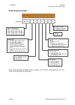
Model Designation Guide
UFD XXX X
X
X
X
X
X
X
X
Example:
UFD 100 4
V
4
A
1
D
2
S
Notes:
When specifying an Applicator with no modules, (see “Z” above)
,
the Module Type (H, V, etc.)
must still be specified for the application.
Service Block Length:
050 1 = (1 port/1 solenoid)
050 2 = 50mm (2 port/1 solenoid)
075 3 = 75mm (3 port/1 solenoid)
100 4 = 100mm (4 port/ 1 solenoid)
150 6 = 150mm (6 port/ 1 solenoid)
Module Type:
A = Vertical Hi-Speed SB (manifold air)
H = Horizontal UFD* (continuous)
V = Vertical UFD* (continuous)
K = Horizontal UFD SB (intermittent)
F = Vertical UFD SB (intermittent)
J = Vertical, Hi-Speed SB, (intermittent)
Festo
M = Horizontal, Hi-Speed SB, (intermittent)
Festo
P = Horizontal Hi-Speed SB (manifold air)
No. of Modules installed:
1, 2, 3, 4, 5, 6 or
Z (no modules)
Voltage:
2 = 240VAC
Control:
D = DynaControl / PLC
M = MCV
N = Upgrade, Nor (Nickel RTD)
L = Upgrade, Mel (J-type thermocouple)
P = Upgrade, Mel (Platinum RTD)
Filter Options:
A = 100 mesh, basket
B = 150 mesh, basket
C = 150 mesh, spin-on
D = 200 mesh, spin-on
Number of Solenoids:
1, 2, 3, 4, 5 or 6
0 = Only for options J, M
E = Adds Balanced Solenoid Manifold
(not available for J, M)
Applicator Options:
S = Standard (No Options)
A = Adds Purge Valve

