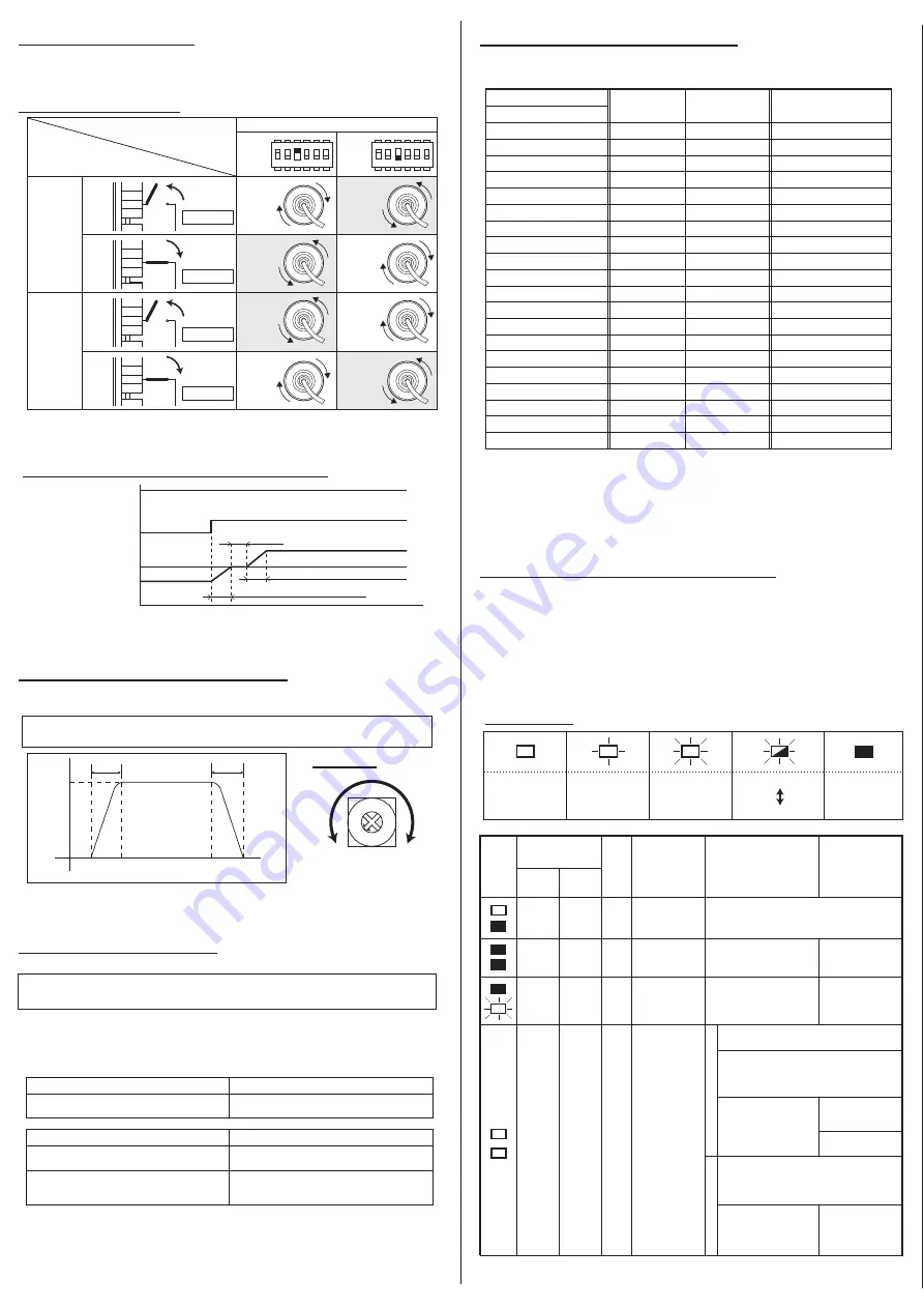
5-2. Direction Setting
8. Error status, Reset and History
5-3. Acceleration and Deceleration
Reverse direction by external DIR signal can be permitted even while motor is running.
Power Moller turning direction can be set or changed either internally by integral DIP
switch or externally by optional switch.
・
Discharged the error signal discharged when power is injected to the driver card
(for 0.5sec) and when power to the driver card is shut off(for 2 seconds)
Error signal is discharged from CN2-4.
6. Error Signal Output
・
Power Moller’s motor pulse signal is discharged from CN2-5.
・
2pulses/motor rotation, NPN open collector output.
・
When error arises, the error can be identified either by LED1(Green) and LED2(Red)
or by the error signal discharged from CN2-4.
・
To reset the error status, first remove the cause of error, and then switch the direction
signal at CN2-2.
・
To restart to Power Moller, first remove the cause of error, and then re-inject RUN
signal at CN2-1.
7. Motor Pulse Signal Output
SW1-4 allows the selection of the error signal discharge timing: discharge on normal
status or discharge when error arise. Error signal is PNP open collector in case of
CBM-105FP.
※
See section 8 for error status, reset and history.
①
※
Protective resistor should be mounted to suppress the output to be 25mA or less,
otherwise the driver card’s integral transistor may e damaged.
※
100
Ω
protective resistor is built-in the driver card output section for error output.
※
Protective resistor should be mounted to suppress the output to be 25mA or less,
otherwise the driver card’s integral transistor may e damaged.
※
100
Ω
protective resistor is built-in the driver card output section for motor pulse
output.
Integral potentiometer VR1 allows the acceleration adjustment from 0 to 2.5seconds.
Integral potentiometer VR2 allows the deceleration adjustment from 0 to 2.5seconds.
①
②
※
Turning direction viewed from the Power Moller’s power cable side.
※
0V should be common to power voltage.
※
7.3mA current is drawn at CN2-2.
※
Reverse direction by DIP switch is prohibited while motor is running. Motor must be
stopped first, and then reverse a direction by DIP switch.
VR(1)
VR(2)
SW1-4 OFF
SW1-4 ON
SW1-6 ON
SW1-6 OFF
Error signal discharges in normal status
Error signal discharges when error arises
PNP open collector output
NPN open collector
Open on normal
Transistor on PCB is ON when error arises
Open on error
Transistor on PCB is OFF when error arises
(
7
)
(
6
)
(
)
(
)
FE
type
FS/FP
type
ON
S W 1 - 3
OFF
・
The adjustable range of time is on the control basis, thus may differs on actual
transfer speed.
Setting for Turning Direction
CW/CCW
Reverse motor direction by external DIR signal. (CN2-2)
CW
CCW
CW
CCW
CCW
CW
CCW
CW
Disconnected
CW/CCW
Connected
Disconnected
Connected
CW/CCW
CW/CCW
VR1
・
VR2
Internal speed variation
SW2
Frequency
(
Hz
)
Motor speed
(
r/min
)
Analog voltage input
(V)
9
166
4969
9.6~9.9
8
152
4556
9.1~9.4
-
145
4349
8.6~8.9
7
138
4141
8.1~8.4
-
131
3934
7.6~7.9
6
124
3727
7.1~7.4
5
110
3313
6.6~6.9
-
104
3106
6.1~6.4
-
97
2899
5.6~5.9
-
90
2692
5.1~5.4
4
83
2485
4.6~4.9
-
76
2278
4.1~4.4
-
69
2071
3.6~3.9
-
62
1864
3.1~3.4
3
55
1657
2.6~2.9
-
48
1450
2.1~2.4
2
41
1242
1.6~1.9
-
35
1035
1.1~1.4
1
28
828
0.6~0.9
0
21
621
0.1~0.4
※
Reset the error by CN2-1(Run signal), the Power Moller start running immediately.
※
In case power is 8.5V or less, the driver card may not work properly.
Speed deviation
:
±3
%
R U N
S TO P
O N
O F F
CN2-2
Reverse
Normal
Deceleration setting time(VR2)
Turning direction
Acceleration setting time(VR1)
0 . 5 S
1
2
3
4
5
6
1
2
3
4
5
6
ERR
V-IN
RUN
DIR
1234
ERR
V-IN
RUN
DIR
1234
ERR
V-IN
RUN
DIR
1234
ERR
V-IN
RUN
DIR
1234
LED indication
Set
Speed
0sec
(Min)
2.5sec
(Max)
Illuminates
Blinks at 1Hz
Blinks at 6Hz
Blink twice at 6Hz
Off for 1.5sec
Off
LED1
(Green)
LED2
(Red)
CN2-4
(
Error signal
)
SW1-4
ON
SW1-4
OFF
Symptom/
Causes
Reset the error signal
Restart the
Power Moller
MDR
Open
Open
Open
Discharge
Discharge
n.a.
n.a.
STOP
Open
STOP
Discharge
Open
STOP
Normal operation
No power
Supply 24VDC power
See section 5
See section 5
PCB damaged
Shut off the power then
replace the driver card
Thermister reacted
(Thermister error)
Automatic recovery setting
Manual recovery setting
Power Moller restart immediately 1 minute
after Thermister recovery from cooling off.
Power Moller restarts by injecting RUN signal
followed by STOP signal to CN2-1 to reset the
error signal then inject RUN signal to CN2-1 to
restart, 1minute after Thermister recovery.
After Thermister recovery,
inject signal ON-OFF-ON
or OFF-ON-OFF order to
CN2-2
Inject signal RUN-
STOP-RUN order to
CN2-1
Restarts automatically
in a minute.
Power Moller restarts by injecting RUN signal
followed by STOP signal to CN2-1 to reset the
error signal then inject RUN signal to CN2-1 to
restart, 1minute after Thermister recovery.
After Thermister recovery,
inject signal ON-OFF-ON
or OFF-ON-OFF order to
CN2-2
Inject signal RUN-
STOP-RUN order to
CN2-1


