24
SLS-SLH 10/06
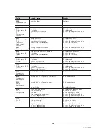
Faulty
Probable cause
Remedy
AL00
See the alarm
Autoreset
Automatic alarm
intervention
AL01
Wrong compressors rotation
To check the electrical connection
Wrong power supply
AL02
Low water flow
To check the pump
Antifreezing
Wrong pump
To check the pump size
Water filter dirty
To clean the filter
Dirty exchanger
To clean the exchanger
High circuit pressure drop
To check the plant pressure drop
AL03
External interlock contact open
To check the electrical connection
Interlock
To check the interlock external contact
AL04
Water pump stop
To check the pump
Luck of flow
Water pump blocked
To release the pump
Pump thermal contact open
To reset the thermal contact and to check
the scale
Flow switch blocked
To release the flow switch
AL05
Espansion valve broken
To replace the espansion valve
Sys 1
Gas circuit empty
To charge the circuit
Low pressure
Gas leak
To find and repair the leak
High temperature water inlet
To check the plant thermal load
Solenoid valve not open
To check the electrical connection
Solenoid valve not open
To check Pump Down setting
AL06
Espansion valve broken
To replace the espansion valve
Sys 2
Gas circuit empty
To charge the circuit
Low pressure
Gas leak
To find and repair the leak
High temperature water inlet
To check the plant thermal load
Solenoid valve not open
To check the electrical connection
Solenoid valve not open
To check Pump Down setting
It is a Simultaneous Global Defrost.
Parameters used: Defrost start Temp; Defrost stop temp,
defrost Delay time, defrost Max time, Reversing Off
Time. It is possible to set compressor switch off time
(Reversing Off parameter) when system enter and exit
from defrost mode. Compressors are not switched off if
time is set to 0 seconds. Moreover cycle reversion dur-
ing normal operation (changing from summer to winter
mode or back) always follow compressors switch off.
If one of the two Tcoil probes temperature values fall
below the Defrost start Temp, a timer starts. The timer is
increased while the Tcoil value is under the Defrost start
Temp. When the timer (t1 + t2 + t3 + …) reaches the
defrost start time value, the defrost cycle starts for both
system.
During defrost cycle, fans are stopped, all compressors
run (if one or more are in off, they must be powered),
reverse valve is powered.
During defrost cycle, if the discharge pressure in one of
the two systems, reaches an high dangerous value, fans
must run at max speed. So, if discharge pressure trans-
ducer are attached, if one of the two high pressure val-
ues reaches the Max Discharge Pressure value (see
MDP) the fans contactor is energized and the analogue
output is forced to 5Vdc. If High Pressure Transducer
are not attached, in HeatPump there will be a High
Pressure Switch each system, connected to the J1-1 and
J1-3. If during defrost, one of these pressure switch con-
tact closes, the fans will run at max speed.
Defrost cycle stops when the Tcoil value rises up to the
Defrost Stop Temp value, anyway if the Defrost Max
Time has elapsed.
When defrost cycle is ended, the reverse valve is un-
powered and fans are powered again, according to
fans rule logic.
17
SLS-SLH TROUBLE SHOOTING
The following table details possible unit faults, their probable cause and suggested remedies, for any other problems
not immediately recognisable and/or technical assistance, call an authorised Technical Service Center.
Summary of Contents for SLS-SLH
Page 1: ...Chiller unit SLS SLH...


