S p e z i a l e l e k t r o n i k G m b H
iseg Spezialelektronik GmbH
Email: [email protected]
Tel ++ 49 (0) 351 / 26 996 - 0
Bautzner Landstr. 23
http://www.iseg-hv.de
Fax ++ 49 (0) 351 / 26 996 - 21
D - 01454 Radeberg/ Rossendorf
13
The device has the following special operating states
Table 3.1: Operating states
Function
Description
Voltage Ramp
The change of the output voltage between the set values and after switching the high voltage on or off are
performed with the set voltage ramp.
Current Ramp
All changes between current set values are performed with the programmed current ramp.
Voltage Limit VLIM
The voltage limit is separated into two functions:
1. Limit the voltage set value to the limit value: 0
≤
V
SET
≤
V
LIM
≤
V
NOM
2. If the measured voltage exceeds the limit value by two percent, the ChannelEventStatus bit EventVolt-
ageLimit is set: V
MEAS
≥
1.02 • V
LIM
The display shows "VLIM" in the status bar.
Current Limit I
LIM
The current limit is separated into two functions:
1. Limit the current set value to the limit: 0
≤
I
SET
≤
I
LIM
≤
I
NOM
2. If the measured current exceeds the limit value by two percent, the ChannelEventStatus bit EventCur-
rentLimit is set: I
MEAS
≥
1.02 • I
LIM
The display shows "ILIM" in the status bar.
Kill-Enable
The following events shut down the high voltage without ramp in mode Kill-Enable: EventConstantCurrent,
EventArc, EventVoltageLimit, EventCurrentLimit.
The display shows “KILL” in the status bar.
Current Trip
In mode Kill-Enable the high voltage will be shut down without a ramp, if the measured current is greater
than the set current: I
MEAS
≥
I
SET
The display shows "TRIP" in the status bar..
Emergency Off
The function emergency off shut down the high voltage without ramp. To turn the high voltage on again, the
state emergency off has to be leaved and the ChannelEventStatus bit EventEmergencyOff must be cleared
afterwards.
The display shows “EMCY” in the status bar.
3.2
Monitoring
Voltage
The single phase mains voltage and the internal auxiliary voltages are monitored. If one of these voltages is out of its limits,
the high voltage generation is stopped.
Warning!
High voltage generation is reactivated immediately if the limit values are no longer exceeded or fallen
below.
For devices of the class GPS with option CLD, the maximum voltage value is monitored by the OVP-comparator. The threshold
is set to approx. 110 percent of nominal voltage at the factory. If this threshold is reached (e.g. through an internal defect),
high voltage generation is stopped.
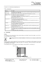
The output power of the unit will be reduced, if the input voltage is smaller than 95 V
AC
(see Figure 3.2).
Input voltage (V
AC
)
Output power %
0
85
90
95
100
260
265
100
95
90
85
75
80


