S p e z i a l e l e k t r o n i k G m b H
iseg Spezialelektronik GmbH
Email: [email protected]
Tel ++ 49 (0)351 / 26 996 - 0
Bautzner Landstr. 23
http://www.iseg-hv.de
Fax ++ 49 (0)351 / 26 996 - 21
12
D - 01454 Radeberg/ Rossendorf
3
Functional description
In the following, the working principle of the power supply will be described:
Next to the mains there is a EMI/RFI filter, which feeds the power factor correction unit (PFC) and the inrush current limitation
circuit. The PFC draws sinusoidal currents from the mains, which are in phase with the supply voltage.
Caution!
With an input voltage greater than 255 V, the PFC only functions as a rectifier and the current
consumption is no longer sinusoidal. In the input voltage range below 100 V, either the output power
or the ambient temperature must be reduced (Figure 4.2).
Furthermore the PFC provides a DC link voltage, that is buffered by an electrolytic capacitor battery. An inverter with a con-
nected resonance circuit transforms the DC-Link voltage into a controllable sinusoidal voltage. The HV transformer and HV
rectifier provide an output voltage corresponding to the external set voltage. Output voltage and current are measured by high
precision voltage dividers and a shunt and are fed back to the control circuit. A damping resistor connected to the output
capacitance limits the output current during a load change or ARC.
High voltage power supplies of this class work with a fixed switching frequency. The output parameters are controlled via a
pulse width modulation (PWM).
The control circuit controls and limits the output voltage and current corresponding to the set values. Normalized monitor
voltages for voltage and current are provided for read back. The control circuit is also monitoring the input voltages, auxiliary
voltages and the temperatures of cooling air and single components.
The power supply is turned ON/OFF with a switch installed at the front panel of the power supply. An ARC-management with
fixed parameters is installed in the power supply.
3.1
Operation states
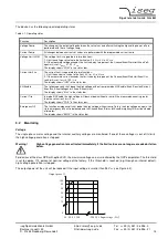
Figure 3.1 shows the operating area of the device. There are two modes for high voltage generation:
1.
Constant voltage control CV:
Control of output voltage according to set value V
set_v
(V
mon_i
< V
set_i
).
2.
Constant current control CC:
Control of output current according to set value V
set_i
(V
mon_v
< V
set_v
).
Figure 3.1: Operating area of the device.
Output voltage
Output current
V
nom
I
nom
0
P
nom
Operating area


