218150 / 948260310020
2015-12-16·BA00·III·en·01
Engineering
11
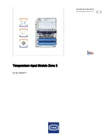
Temperature Input Module Zone 2
Series 9482/33
EN
EN
EN
EN
EN
EN
EN
EN
EN
EN
EN
EN
EN
EN
EN
EN
EN
EN
EN
EN
EN
EN
EN
EN
EN
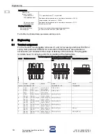
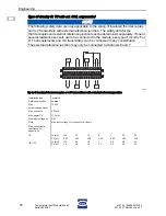
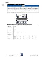
Connection example
Up to 8 thermocouples or mV transmitters as well as resistance temperature detectors
and an external reference junction are connected.
A mixture of different signals is possible, for example:
•
thermocouples or mV sources on channel 0, 2, 6 and 7
• Resistance temperature detectors or resistance teletransmitters on channel 1, 3 and 5
•
external reference junction on channel 6 and 7
16497E00
NOTE
The signal inputs are galvanically connected with each other. Since they are designed
as differential inputs, they prevent generation of ground loops for grounded
thermocouples.
NOTE
With the exception of the external CJC (channel 6 and 7), signals can be mixed up
arbitrarily!
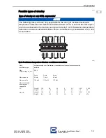
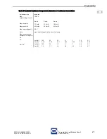
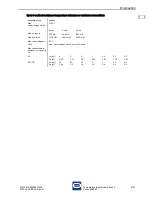
Channel
RTD and potentiometer with thermocouples and mV transmitters with external CJC
Thermocouple / mV sen
-
sor
2-wire RTD
3-wire RTD
external 3-wire CJC /
3-wire RTD
Terminals
0
2 (V+), 3 (V-)
--
--
--
1
6 (V+), 7 (V-)
--
--
--
2
--
--
9 (I+), 11 (V-), 12 (I-)
--
3
--
13 (I+), 16 (I-)
--
--
4
--
--
--
17 (I+), 18 (V+),
19 (V-), 20 (I-)
5
--
--
--
21 (I+), 22 (V+),
23 (V-), 24 (I-)
6
26 (V+), 27 (V-)
--
--
25 (I+), 29 (I+),
32 (I-)
7
30 (V+), 31 (V-)
--
--
NOTE
The safety data of the connection example are determined depending on the type of
circuitry I!
17
18
19
20
21
22
23
24
25
26
27
28
29
30
31
32
1
2
3
4
5
6
7
8
9
10
11
12
13
14
15
16
mV
T
T
T
T
Summary of Contents for 9482/33
Page 2: ......

