


Parameterization and commissioning
30
218150 / 948260310020
2015-12-16·BA00·III·en·01
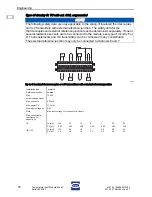
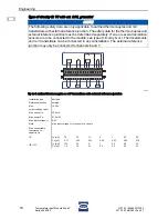
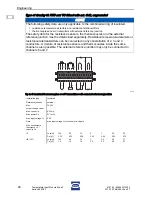
Temperature Input Module Zone 2
Series 9482/33
EN
EN
EN
EN
EN
EN
EN
EN
EN
EN
EN
EN
EN
EN
EN
EN
EN
EN
EN
EN
EN
EN
EN
EN
EN
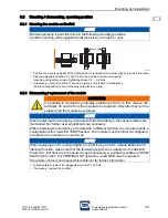
• Pull out the terminals from the module
• Pull the blue notch lever of the module upwards to unlock the module
• Remove the module vertically from the BusRail
• Position the new module vertically onto the BusRail and snap into place by slightly pressing it
• If necessary, snap the partition into place between the modules
•
Plug the pluggable terminals X1 and X2 into the module and secure them against
loosening using screws (tightening torque 0.5 ... 0.6 Nm)
8.3
Installation
•
Connect the field devices to the pluggable terminals X1 and X2 according to terminal assignment (see
chapter Project Engineering or insert disc on the inside of the
protective cover) (tightening torque for the screw-type terminals 0.5 ... 0.6 Nm)
• Place the field wiring shields (if available) as close to the entry point on the grounding rail as possible.
•
Plug the pluggable terminals X1 and X2 into the module and secure them against
loosening using screws. (Tightening torque 0.5 … 0.6 Nm)
9
Parameterization and commissioning
No parameterization has to be carried out on the module.
Before commissioning, make sure that:
•
the device has been installed according to regulations,
• the cables have been connected correctly,
• the device and the connection cables are not damaged,
•
the screws in the terminals have been tightened firmly. Make sure, that the correct tightening torque is
used (chapter "Installation").
WARNING
The national installation instructions (e.g. IEC/EN 60079-14) must be
observed. Intrinsically safe and non-intrinsically safe field circuits must not be
led in a common cable duct! Make sure that there is a distance of at least 50
mm (safety distance) between the connecting units of intrinsically safe and
non-intrinsically safe circuits!
NOTE
In the protective cover, there is an insert disc which can be used to enter the assignment
of the field devices to the channels. Labelling of the insert disc can be performed,
for example by means of the IS Wizard.
NOTE
The module and the pluggable terminals X1 and X2 can be safely connected or
disconnected during operation in the hazardous area (hot swap). Mounting can be
carried out with connected or disconnected terminal.
DANGER
Explosion hazard due to incorrect installation!
Non-compliance results in severe or fatal injuries.
•
Check the device for proper installation and function before commissioning.
•
Comply with the national regulations.
Summary of Contents for 9482/33
Page 2: ......


