background image

218150 / 948260310020

2015-12-16·BA00·III·de·01

Projektierung

23

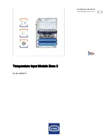
Temperatur Input Modul Zone 2

Reihe 9482/33

DE
DE
DE
DE
DE
DE
DE
DE
DE
DE
DE
DE
DE
DE
DE
DE
DE
DE
DE
DE
DE
DE
DE
DE
DE

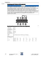
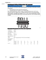
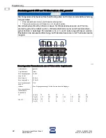
Bis zu 8 geerdete Widerstandsthermometer oder Widerstandsgeber

Installationsart

geerdet

Max. Ausgangsspan

-

nung Uo ext

12,92 V

Max. Strom Io
Max. Leistung Po
Max. anschließbare 

Induktivität Lo / 

KapazitätCo
Max. Eingangsspan

-

nung Ui

6,5 V

Hinweis

Max. Eingangsspannung Ui ist die Summe über alle Eingänge

IIC

IIB / IIIC

2 Leiter

3 Leiter

4 Leiter

47,9 mA

58,5 mA

68,8 mA

155,0 mW

189,0 mW

220,0 mW

Lo [mH]

9

5

2

1

0,5

0,2

0,1

Co [

m

F]

0,23

0,31

0,41

0,50

0,60

0,76

0,93

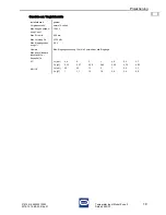
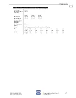
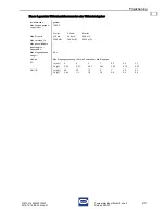
Lo [mH]

40

20

10

5

1

0,5

0,1

Co [

m

F]

0,94

1,3

1,6

1,9

2,9

3,4

5,6

Summary of Contents for 9482/33

Page 1: ...DE EN DE EN DE EN DE EN DE EN DE Betriebsanleitung Operating instructions Additional languages www stahl ex com DE EN Temperatur Input Modul f r Zone 2 Temperature Input Module for Zone 2 Reihe 9482...

Page 2: ......
Page 3: ...DE DE DE DE DE DE DE DE DE DE DE DE DE DE DE DE DE DE DE DE DE DE DE DE DE Betriebsanleitung Additional languages www stahl ex com DE Temperatur Input Modul Zone 2 Reihe 9482 33...

Page 4: ...nd nderungen 5 4 Funktion und Ger teaufbau 5 4 1 Funktion 5 4 2 Ger teaufbau 6 5 Technische Daten 6 6 Projektierung 11 6 1 Anschlussbelegung 11 6 2 Nachweis der Eigensicherheit 12 7 Transport und Lage...

Page 5: ...015 12 16 BA00 III de 01 1 3 Weitere Dokumente Datenblatt 9482 33 Kopplungsbeschreibung IS1 Download unter www stahl ex com Weitere Sprachen siehe www stahl ex com 1 4 Konformit t zu Normen und Bestim...

Page 6: ...Betriebsanleitung sorgf ltig lesen und am Einbauort des Ger ts aufbewahren Mitgeltende Dokumente und Betriebsanleitungen der anzuschlie enden Ger te beachten GEFAHR Gefahren f r Personen Nichtbeachtun...

Page 7: ...t eigensicheren Feldstromkreisen ist ein Abstand von 50 mm einzuhalten Module mit eigensicheren und nicht eigensicheren Feldstromkreisen d rfen gemischt auf einer BusRail betrieben werden Hierbei sind...

Page 8: ...tbruch und Kurzschluss berwacht Die Schnittstelle des Temperatur Input Moduls zum internen Datenbus der BusRail ist redundant ausgef hrt Kompatibler Ersatz f r IS1 Remote I O Module Reihe 9480 12 und...

Page 9: ...180 C 0 1 K Ni500 DIN 43760 60 180 C 0 1 K Ni1000 DIN 43760 60 180 C 0 1 K Pt462 GOST 6651 94 200 1100 C 0 15 K Pt502 GOST 6651 94 200 1100 C 0 15 K Pt1001 GOST 6651 94 200 1100 C 0 1 K Cu532 GOST 665...

Page 10: ...ung gem Norm EN 60079 11 Zwischen Hilfsenergie Systemkomponenten 1500 V AC Zwischen zwei I O Modulen 500 V AC Zwischen I O Kan len Systemkomponenten Zwischen I O Kan len Systemkomponenten 500 V AC Typ...

Page 11: ...OST Signal Verhalten im Fehlerfall letzten Wert halten Fehler berwachung EIN AUS Sensortyp siehe Tabelle Anschlie bare Sensoren Schaltungsart 2 3 4 Leiter Umgebungsbedingungen Umgebungstemperatur 40 7...

Page 12: ...triebsanleitung beachten Montageart auf 35 mm DIN Schiene NS 35 15 DIN EN 60715 Anschlussbelegung steckbare Klemmen X1 und X2 Sensor Widerstandssensoren Thermoelemente und mV Geber externe Vergleichss...

Page 13: ...cherheitstechnischen Daten angegeben F r alle verwendeten Sensoren m ssen entsprechend den im Folgenden aufgef hrten HINWEIS Die Signaleing nge sind untereinander galvanisch verbunden Da sie als Diffe...

Page 14: ...kanal Das Flussdiagramm dient zur richtigen Auswahl der sicherheitstechnischen Daten 16556E00 Flussdiagramm zur Auswahl der sicherheitstechnischen Daten Begriffserkl rung RTD Widerstandsthermometer un...

Page 15: ...m Modul angeschlossen werden siehe Beschaltungsart F oder H Widerstandsthermometer und Widerstandsferngeber k nnen in beliebiger Konstellation von 2 3 und 4 Leiter angeschlossen werden Hinweis keine T...

Page 16: ...sensoren ebenfalls an dem Modul angeschlossen werden siehe Beschaltungsart F oder H Thermoelemente und mV Geber k nnen in beliebiger Konstellation angeschlossen werden Installationsart isoliert Vergle...

Page 17: ...ensoren ebenfalls an dem Modul angeschlossen werden siehe Beschaltungsart G oder I Thermoelemente und mV Geber k nnen in beliebiger Konstellation angeschlossen werden Installationsart geerdet Vergleic...

Page 18: ...in oder mehrere Widerstands sensoren ebenfalls an dem Modul angeschlossen werden siehe Beschaltungsart F oder H Thermoelemente und mV Geber k nnen in beliebiger Konstellation angeschlossen werden Die...

Page 19: ...ationsart isoliert Vergleichsstelle extern 3 Leiter Max Ausgangsspan nung Uo ext 12 92 V Max Strom Io 17 4 mA Max Leistung Po 56 2 mW Max Eingangsspan nung Ui 6 5 V Hinweis Max Eingangsspannung Ui ist...

Page 20: ...n oder mehrere Widerstands sensoren ebenfalls an dem Modul angeschlossen werden siehe Beschaltungsart G oder I Thermoelemente und mV Geber k nnen in beliebiger Konstellation angeschlossen werden Die e...

Page 21: ...lationsart geerdet Vergleichsstelle extern 3 Leiter Max Ausgangsspan nung Uo ext 12 92 V Max Strom Io 68 6 mA Max Leistung Po 222 0 mW Max Eingangsspan nung Ui 6 5 V Hinweis Max Eingangsspannung Ui is...

Page 22: ...ndssensoren und Thermo elemente getrennt ermittelt werden Widerstandsthermometer und Widerstandsfern geber k nnen in beliebiger Konstellation von 2 3 und 4 Leiter angeschlossen werden Ebenfalls ist di...

Page 23: ...tallationsart isoliert Max Ausgangsspan nung Uo ext 12 92 V Max Strom Io Max Leistung Po Max anschlie bare Induktivit t Lo Kapazit tCo Max Eingangsspan nung Ui 6 5 V Hinweis Max Eingangsspannung Ui is...

Page 24: ...dssensoren und Thermo elemente getrennt ermittelt werden Widerstandsthermometer und Widerstandsfern geber k nnen in beliebiger Konstellation von 2 3 und 4 Leiter angeschlossen werden Ebenfalls ist die...

Page 25: ...tallationsart geerdet Max Ausgangsspan nung Uo ext 12 92 V Max Strom Io Max Leistung Po Max anschlie bare Induktivit t Lo Kapazit tCo Max Eingangsspan nung Ui 6 5 V Hinweis Max Eingangsspannung Ui ist...

Page 26: ...etrennt ermittelt werden Widerstandsthermometer und Widerstandsferngeber k nnen in beliebiger Konstellation von 2 3 und 4 Leiter angeschlossen werden Ebenfalls ist die kanalweise Mischung von Widersta...

Page 27: ...are Induktivit t Lo Kapazit tCo IIC IIB IIIC Installationsart isoliert Vergleichsstelle extern 3 Leiter Max Ausgangsspan nung Uo ext 12 92 V Max Strom Io 17 4 mA Max Leistung Po 56 2 mW Max Eingangssp...

Page 28: ...trennt ermittelt werden Widerstandsthermometer und Widerstandsferngeber k nnen in beliebiger Konstellation von 2 3 und 4 Leiter angeschlossen werden Ebenfalls ist die kanalweise Mischung von Widerstan...

Page 29: ...Bereichen der Zone 22 zugelassen Installationsart geerdet Max Ausgangsspan nung Uo ext 12 92 V Max Strom Io Max Leistung Po Max Eingangsleistung Ui 6 5 V Hinweis Max Eingangsspannung Ui ist die Summe...

Page 30: ...Unfallverh tungsvorschriften durchf hren damit der Explosionsschutz erhalten bleibt Das Ger t nur durch geschultes Fachpersonal installieren lassen Dazu sind Kenntnisse der einschl gigen Normen z B I...

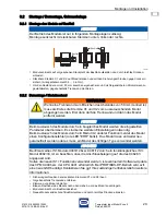
Page 31: ...Betrieb des Moduls ist nur in folgenden Montagelagen zul ssig Montage senkrecht mit steckbaren Klemmen unten links oder rechts WARNUNG Wenn eine Trennwand zum Erreichen des Abstandes von 50 mm montier...

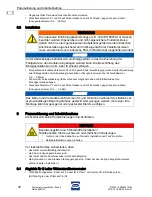
Page 32: ...ben an den Klemmen fest angezogen sind Dabei auf das richtige Anzugsdrehmoment achten Kapitel Installation 9 1 Abgleich f r 2 Leiter Widerstandthermometer TIM 9482 konfigurieren Kanal auf 2 Leiter R i...

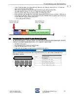
Page 33: ...ed gemeldet dann wurde der 2 Leiter Abgleich Vorgang fehlerhaft beendet Neuen Abgleich durchf hren 16557E01 9 2 Potentiometer im schnell 4 Leiter Betrieb Joystick In dieser Betriebsart 4 kanal schnell...

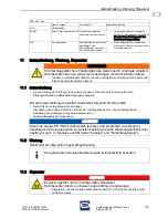
Page 34: ...n Datenverkehr mit dem Master in Betrieb setzten Master Busverbindung und CPM oder CPU PM pr fen AUS Keine Funktion Keine Versorgungs spannung am I O Modul vorhanden oder I O Modul defekt System Verso...

Page 35: ...Umgebungstemperatur verringern durch z B Beschattung oder K hlung Hinweis Ohne Behebung wird das Modul dauerhaft gesch digt EIN Wartungsbedarf Steckplatzfehler oder Modul gesch digt durch bertemperatu...

Page 36: ...nterladen und ausf llen Ger t zusammen mit dem Serviceschein wieder in der Originalverpackung an die R STAHL Schaltger te GmbH senden 12 Entsorgung Nationale und lokal g ltige Vorschriften und gesetzl...

Page 37: ...EN EN EN EN EN EN EN EN EN EN EN EN EN EN EN EN EN EN EN EN EN EN EN EN EN Operating instructions Additional languages www stahl ex com EN Temperature Input Module Zone 2 Series 9482 33...

Page 38: ...terations 5 4 Function and device design 5 4 1 Function 5 4 2 Device design 6 5 Technical data 6 6 Engineering 15 6 1 Terminal assignment 15 6 2 Proof of intrinsic safety 18 7 Transport and storage 34...

Page 39: ...blication Code 2015 12 16 BA00 III en 01 1 3 Further documents Data sheet 9482 33 Coupling description IS1 download from www stahl ex com For further languages see www stahl ex com 1 4 Conformity with...

Page 40: ...ead the operating instructions carefully and store them at the mounting location of the device Observe applicable documents and operating instructions of the devices to be connected DANGER Danger to p...

Page 41: ...trinsically safe field circuits Modules with intrinsically safe and non intrinsically safe field circuits may be operated simultaneously on one BusRail In this case a distance of 50 mm must be maintai...

Page 42: ...ndividually monitored for wire breakage and short circuit The interface of the Temperature Input Module to the internal data bus of the BusRail is designed redundantly Compatible spare for IS1 remote...

Page 43: ...51 200 850 C 0 1 K Pt1000 IEC 60751 200 850 C 0 1 K Ni100 DIN 43760 60 180 C 0 1 K Ni500 DIN 43760 60 180 C 0 1 K Ni1000 DIN 43760 60 180 C 0 1 K Pt462 GOST 6651 94 200 1100 C 0 15 K Pt502 GOST 6651 9...

Page 44: ...st voltage acc to standard EN 60079 11 Between auxiliary power system components 1500 V AC Between two I O modules 500 V AC Between I O channels system components 500 V AC Between I O channels ground...

Page 45: ...ype see table connectable sensors Type of connection 2 3 4 wire Ambient conditions Ambient temperature 40 75 C observe operating instructions Storage temperature 40 80 C Maximum relative humidity 95 w...

Page 46: ...rizontal or vertical observe operating instructions Mounting type on 35 mm DIN rail NS 35 15 DIN EN 60715 Terminal assignment of the pluggable terminals X1 and X2 sensor Resistance sensors Thermocoupl...

Page 47: ...00 NOTE The signal inputs are galvanically connected with each other Since they are designed as differential inputs they prevent generation of ground loops for grounded thermocouples NOTE With the exc...

Page 48: ...nding on the circuitry the safety data for the respective measurement channel may vary The flow chart will help you select the correct safety data Flow chart for selection of the safety data Explanati...

Page 49: ...es are to be connected to the module see type of circuitry F or H Resistance temperature detectors or resistance teletransmitters can be connected in any constellation of 2 3 and 4 conductors Note no...

Page 50: ...resistance sensors are to be connected to the module see type of circuitry F or H Thermoelements and mV transmitters can be connected in any constellation Installation type insulated Reference junctio...

Page 51: ...esistance sensors are to be connected to the module see type of circuitry G or I Thermoelements and mV transmitters can be connected in any constellation Installation type earthed Reference junction i...

Page 52: ...eparately If one or several resistance sensors are to be connected to the module see type of circuitry F or H Thermoelements and mV transmitters can be connected in any constellation The external refe...

Page 53: ...unction Installation type insulated Reference junction external 3 wire Max output voltage Uo ext 12 92 V Max current Io 17 4 mA Max power Po 56 2 mW Max input voltage Ui 6 5 V Note max input voltage U...

Page 54: ...y If one or several resistance sensors are to be connected to the module see type of circuitry G or I Thermoelements and mV transmitters can be connected in any constellation The external reference ju...

Page 55: ...junction Installation type earthed Reference junction external 3 wire Max output voltage Uo ext 12 92 V Max current Io 68 6 mA Max power Po 222 0 mW Max input voltage Ui 6 5 V Note max input voltage U...

Page 56: ...sistance sensors and the thermocouples must be determined separately Resistance temperature detectors or resistance teletransmitters can be connected in any constellation of 2 3 and 4 conductors A mix...

Page 57: ...tance transmitters Installation type insulated Max output voltage Uo ext 12 92 V Max current Io Max power Po Max input voltage Ui 6 5 V Note max input voltage Ui is the sum of all inputs Max connectab...

Page 58: ...istance sensors and the thermocouples must be determined separately Resistance temperature detectors or resistance teletransmitters can be connected in any constellation of 2 3 and 4 conductors A mixt...

Page 59: ...ance transmitters Installation type earthed Max output voltage Uo ext 12 92 V Max current Io Max power Po Max input voltage Ui 6 5 V Note max input voltage Ui is the sum of all inputs Max connectable...

Page 60: ...ference junction must be determined separately Resistance temperature detectors or resistance teletransmitters can be connected in any constellation of 2 3 and 4 conductors A mixture of resistance sen...

Page 61: ...ax connectable in ductance Lo capacity Co IIC IIB IIIC Installation type insulated Reference junction external 3 conductors Max output voltage Uo ext 12 92 V Max current Io 17 4 mA Max power Po 56 2 m...

Page 62: ...erence junction must be determined separately Resistance temperature detectors or resistance teletransmitters can be connected in any constellation of 2 3 and 4 conductors A mixture of resistance sens...

Page 63: ...o Max power Po max input power Ui 6 5 V Note max input voltage Ui is the sum of all inputs Max connectable in ductance Lo capacity Co IIC IIB IIIC Installation type earthed Reference junction external...

Page 64: ...losion protection is impaired Carry out installation strictly according to the instructions and national safety and acci dent prevention regulations to maintain the explosion protection The device mus...

Page 65: ...the following mounting positions Vertical mounting with pluggable terminals below on the left or right WARNING If a partition is mounted to guarantee a distance of 50 mm first remove the terminals X1...

Page 66: ...commissioning No parameterization has to be carried out on the module Before commissioning make sure that the device has been installed according to regulations the cables have been connected correctl...

Page 67: ...D on the I O module ON and Error 2 wire calibration failed is signalled in the automation system the 2 wire compensation process has not been completed correctly Perform a new compensation 16557E01 9...

Page 68: ...clic data transfer with the master Check master bus connection and CPM or CPU PM OFF No function No supply voltage at the I O module or I O module is defective Check the system supply Check the CPM or...

Page 69: ...le solution OFF Normal operation FLASHES External maintenance re quired Ambient temperature is outside the specification Reduce ambient temperature for example by means of shading or cooling Note If t...

Page 70: ...iginal packaging to R STAHL Schaltger te GmbH 12 Disposal Observe national and local regulations and statutory regulation regarding disposal Separate materials when sending it for recycling Ensure env...

Page 71: ...218150 948260310020 2015 12 16 BA00 III en 01 Accessories and Spare parts 35 Temperature Input Module Zone 2 Series 9482 33 EN EN EN EN EN EN EN EN EN EN EN EN EN EN EN EN EN EN EN EN EN EN EN EN EN...

Reviews: