


IPU 40108
Page 5 of 29
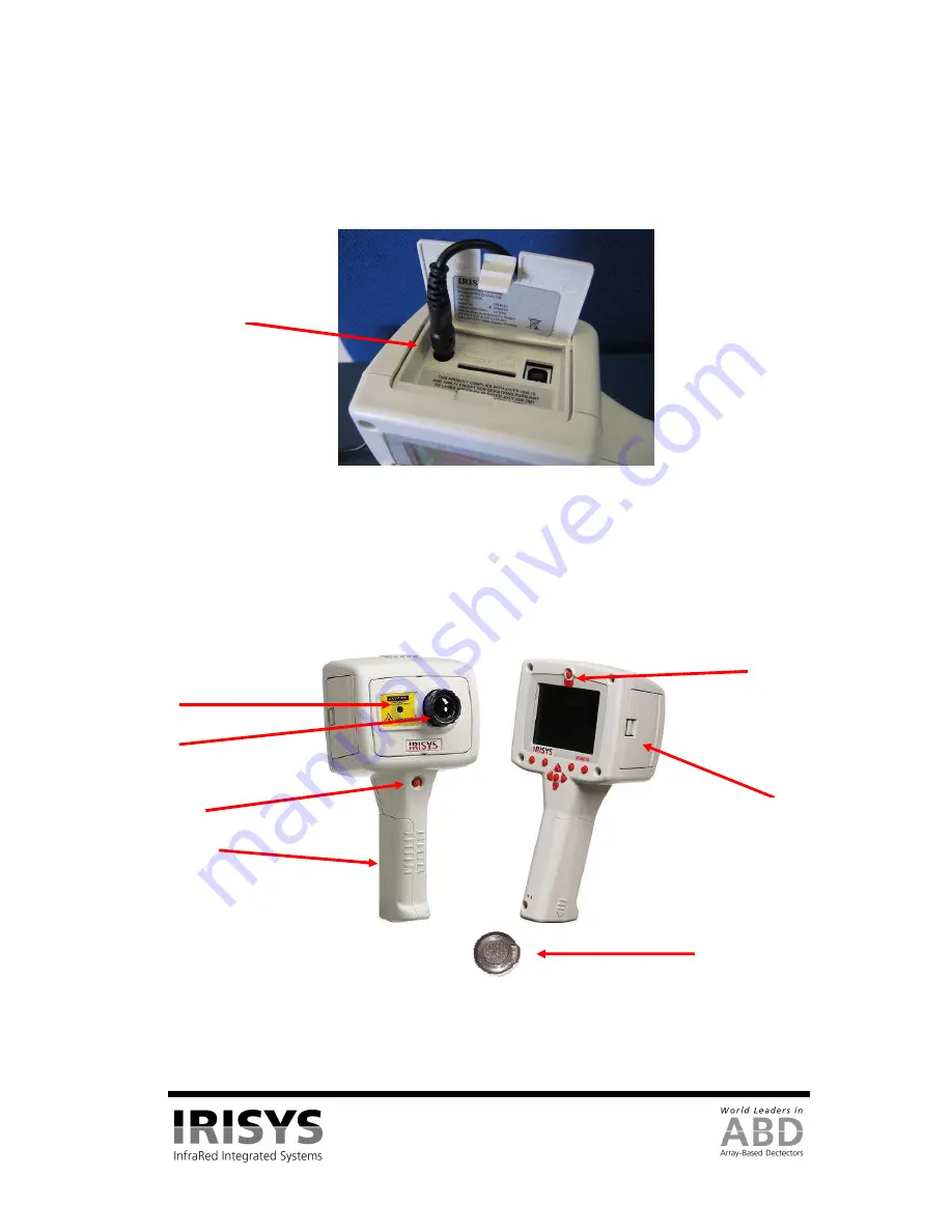
2.2.3
Battery Charging
•
The IRI 4010’s battery can be charged in the imager by inserting the included 12V power supply into
the DC socket under the cover on the side of the IRI 4010 imager; see Figure 4. It takes
approximately 4 hours to fully charge a fully depleted battery if the imager is switched off. Charging
the battery with the imager switched on takes longer.
Figure 4: Connecting the Mains AC Power Supply
3
Operating the IRI 4010 Thermal Imager
3.1
Hardware
The IRI 4010 system is designed for use as a handheld thermal imager. Thermal images stored on the
supplied memory card can be transferred to a PC or laptop computer using the supplied memory card reader.
PC software is supplied for viewing and analysis of saved thermal images.
Figure 5: The IRI 4010 Hardware.
Safety notice: The laser used in this device is designated Class 2.
Under no circumstances should personnel look straight into the laser.
Lens
Laser Pointer
Aperture
Battery
Compartment
Laser Pointer
Button
Power Button
Slots (see Figure 4).
Lens Cap
DC Socket


