background image


   iPOWER TPD-800A User Manual 


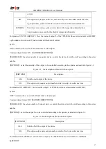
the SER port of the first slave TPD-800A, then use one end of another wire connects to the LINK port of the first 

slave  TPD-800A, the other end connects to the SER port of the next slave  TPD-800A. Use the same way to 

connect other slave TPD-800A. 

9.4 One end of the network wire connects to the net port of the PC; the other end connects to the NET port of the 

TPD-800A, then through IE to access. (Details please refers to the software introduction) 

10. Radicalized Connection Method   


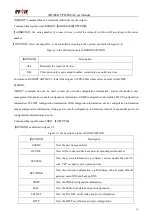
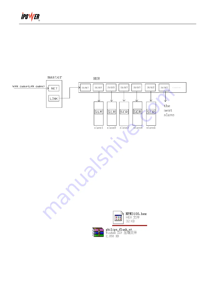
10.1 Set one TPD-800A as master and the others as slaves. One master can link 9pcs TPD-800A slave at most 

10.2 One end of the network wire connects to the net port of the PC; the other end connects to the NET port of 

the TPD-800A   

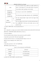
10.3 One end of the network wire connects to the LINK port of the master TPD-800A, the other end connects to 

the RJ-45 port of the HUB (special HUB for TPD-800A link from our company) 

10.4 Use the end of another network wire connects to another in/out port of the HUB, the other end connects to 

the SER port of the slave. Each in/out port of HUB connects to the SER port of one slave TPD-800A, can link 

9pcs slave at most.   

10.5 Through IE to access (Details please refers to the software introduction) 

11. Software Upgrade in Hardware 

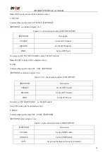
11.1Our company will provide the file of software upgrade

please save it in your PC 

11.2 Please open the software upgrade file                          

then double click this file to install 

the software. 

Summary of Contents for TPD-800A

Page 1: ...iPOWER TPD 800A User Manual 1 iPOWER TPD 800A User Manual ...

Page 2: ...logging Smoke Monitoring 5 4 Outlet Fault Monitoring 5 5 Individual Current Total Current Temperature Humidity Over Limit Monitoring 5 6 Self checking Parameter Monitoring 5 7 Stopping Alarm Monitoring 5 8 Master Slave TPD 800A Configuration 6 9 Daisy chain Connection Method 6 10 Radialized Connection Method 6 11 Software Upgrade in Hardware 7 Ⅶ Software Introduction 8 1 Software Overview 8 2 Acce...

Page 3: ...mit of total load current individual load current May not support this version and temperature humidity 5 System default alarming system alarming when total load current individual load current beyond the limit May not support this version individual outlet breaks down smoke appears water logging or door opening 6 Alarming methods problem information show on LED screen and TPD 800A buzzer alarms t...

Page 4: ...for 110VAC and 220VAC power supply can meet the customers different requirements all over the world Ⅳ Product Picture Description 1 Port1 The software upgrade port of hardware 2 LINK when daisy chain TPD 800A connect with the SER port of the next TPD 800A 3 SER for daisy chain 4 NET 10 100Mbps Ethernet RJ 45 Connector to connect PC Hub router or switch 5 No 2 select outlet 6 RESET set master or sl...

Page 5: ...for example9 600 TPD 800A default address For example ABC DEF TPD 800A series for example310 1 d socket quantity for example OU7 08 finally display the value of which OUTLET No 1 pointing to for example A1 0 0 and RUN indicator flashes M S indicator on means this TPD 800A is master while off means slave TPD 800A 2 Current voltage temperature humidity Monitoring OUTLET No 1 and OUTLET No 2 are toge...

Page 6: ...stop alarming for one minute When TPD 800A has alarm information OUTLET No 1 has no function you have to stop the alarming for one minute then you can check other information But it will continue alarming after one minute until you have modified the fault 8 Master Slave TPD 800A Configuration Press the RESET button for 12 seconds the interval of RUN light is 2 seconds the indicator of M S on indic...

Page 7: ...e end of the network wire connects to the net port of the PC the other end connects to the NET port of the TPD 800A 10 3 One end of the network wire connects to the LINK port of the master TPD 800A the other end connects to the RJ 45 port of the HUB special HUB for TPD 800A link from our company 10 4 Use the end of another network wire connects to another in out port of the HUB the other end conne...

Page 8: ...k in add the file 11 7 Power on the TPD 800A 11 8 Click it will show when read successfully if fails please check the connection wire and the communication port 11 9 Click it will show when erase succeeds If fails please check the connection wire and the communication port 11 10 Click it will show when uploading the file succeeds if fails please check the connection wire and the communication port...

Page 9: ...ith the correct user name and password The system will automatically log out if the user input the incorrect user name or password for three times consecutively The administration interface is made up of three parts the system information interface user guide menu and the device control interface The system information interface mainly contain the company Logo as well as the device current IP addr...

Page 10: ... of door Not found means no door sensors are connected The word open in red on the screen will flash if the door is opened c Smoke alarm displays the connection of smoke sensor Not found means no smoke alarm is connected The word CLOSE or OPEN can be read on the screen if connected The word YES in red will flash if smoke alarm happens d Water logging displays the status of water sensor Not found m...

Page 11: ... temperature humidity threshold and ensure the devices operation well in normal status details as below a Individual outlet current rate 0 10 A total current rate 0 16 A or 0 32 A connecting to the load the device will alarm when the current exceed the set limiting value of current b Temperature rate setting 40 215 Humidity rate 0 100 100 the sensor will alarm when the temperature humidity exceed ...

Page 12: ...ding Note Please fill in correct DNS on Network Config interface E mail alarm function only support non encrypted e mail does not support encrypted e mail 8 Alarm Logs Automatically record the alarm information and data offer viewing and leading out function details as below a Daily record the alarm and recovering information of current overload temperature humidity from exceeding limitation probl...

Page 13: ... offer read only channel mark of visiting the MIB object set community is to offer the read write channel mark of visiting MIB object TRAP community is the style mark of all TRAP information generated and sent The default status of these three items is public private private The length of the community string must be between 1 24 bytes c Set calculagraph of SNMP trap from 1 to 65535 seconds better...

Page 14: ...sor status device configuration information network configuration power on off automatically limiting value to alarm setting alarm setting daily record information and so on 15 Restart Restart interface is designed to restart and refresh the device software system e g Change the IP address HTTP port Telnet port software update no need to cut off the power supply as this operation does not affect t...

Page 15: ...ature of temperature sensor 1 Humidity 1 Display the current connection status and humidity of humidity sensor 1 Temperature 2 Display the current connection status and temperature of temperature sensor 2 Humidity 2 Display the current connection status and humidity of humidity sensor 2 Temperature 3 Display the current connection status and temperature of temperature sensor 3 Humidity 3 Display t...

Page 16: ...also be employed to safe direct connecting devices The configuration and client of SSH require using the PC client agent lots of free shared software like PUTTY are available or user can buy the SSH client in the market The SSH monitor control and manage the device mainly through command line like STATUS ON OFF REBOOT SHOW SET ADD REMOVE RESET RESTART QUIT 1 STATUS STATUS command line can be used ...

Page 17: ... the output to be controlled according to the options as detailed in figure 3 2 Figure 3 2 the description table of switch on option For instance ON ABCEDF 1 Switch on the output 1 of TPD 800A whose series number is ABCDEF 3 OFF OFF command line can switch off individual or total output Command input format OFF ADDRESS OPTION ADDRESS the series number of connect device control the status of switch...

Page 18: ...ice configuration information output configuration information timing power on off configuration information interval of sequential power on configuration information and so on Command line input format SHOW OPTION OPTION as detailed in figure 3 5 Figure 3 5 the description table of SHOW OPTION OPTION Description USERS View the user name and level DEVICE View all the connected devices and correspo...

Page 19: ...r at a time For instance SHOW USER view user information and level 6 SET SET command line can configure and control the IP SUBNET GATEWAY DNS1 DNS2 HTTP TELNET SSH SNMP MAIL THRESHOLD TIMIGN ONNTERVAL of the device A Network configuration Network configuration include IP address Sub net mask Gateway DNS1 and DNS2 Command line input format SET Network configuration For instance SEG IP 192 168 1 163...

Page 20: ...ll be valid after reboot D SSH Command line input format SET SSH OPTION OPTION as detailed in figure 3 6 d Figure 3 6 d the description table of SSH OPTION For instance SET SSH ENABLE set the SSH enable Note SSH setting will be valid after reboot E SNMP Command line input format SET SNMP OPTION OPTION detail as figure 3 6 e Figure 3 6 e the description table of SNMP OPTON OPTION Description ENABLE...

Page 21: ...ut format SET SNMP OPTION OPTION as detailed in figure in 3 6 f Figure 3 6 f the description table of MAIL OPTION OPTION Description ENABLE Enable e mail alarm DISABLE Disable e mail alarm POP3 Setting POP3 e mail receive server SMTP Setting SMTP e mail sending server PORT E mail sending sever port AUTH The authentication of mailbox login USER E mail sending address PASSWORD The password of e mail...

Page 22: ...e of temperature sensor 3 HUM3 L Set the lowest value of humidity sensor 3 H Set the highest value of humidity sensor 3 NO L Set the lowest value of each output current H Set the highest value of each output current TOTAL L Set the lowest value of the total load current H Set the highest value of the total load current TOTALA L Set the lowest value of the total load current of phase A H Set the hi...

Page 23: ...ur clock Week reference table week Monday Tuesday Wednesday Thursday Friday Saturday Sunday Command line 01 02 03 04 05 06 00 The time setting of output Command line input format SET TIMING ADDRESS 1 Y ON 0912301456 1 the outlet No Y daily timing repeat Y means repeat N means non repeat ON the status of switch on off ON means power on OFF means power off 0912301456 the time of power on off format ...

Page 24: ...digits The length of output name can reach 35 byte The are required if there is a blank in the name 7 ADD ADD is the command line of adding device Command line input format ADD DEVICE NO NO the device rank number can be used here one rank number at a time For instance ADD DEVICE 2 ABCDEF the series number of new added device 2 is ABCDEF 8 REMOVE REMOVE command line can be used to delete the connec...

Page 25: ...several Slaves M S indicator on is the Master while off is Slave make sure the device are connected in the right way Master setting Press RESET button for 12 seconds the interval of RUN light is 2 seconds setting success when M S light on Slave setting Press RESET button for 6 seconds the interval of RUN light is 2 seconds setting success when M S light off 3 2 Software setting There are three way...

Page 26: ...ce information after logging on to the administrator interface A 1 Check the device series number through Device Configuration interface make sure the device series number is exactly the same with the hardware 2 Check whether the hardware device is the Master or not the Slaves can not be monitored when single device connected to network multiple devices daisy chain set up one device to be Master o...

Reviews: