


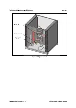


Piping and Instruments Diagram
Page 25
Operating manual LC 340.01-A.3.5/6
Current revision status: Apr 4, 2019
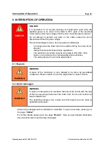
6.2 Hydraulic module
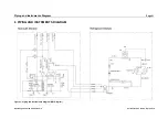
Figure 7: P&I Diagram hydraulic module
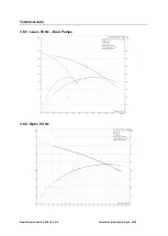
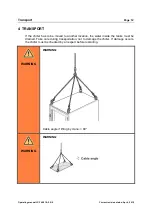
6.2.1 Laser cooling circuit
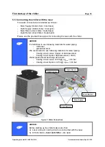
The cooling water for the laser circuit is supplied by the pumps (M4.1 & M4.2). If the
cooling water temperature is too low, the heater (E1) will heat up the water to the
required temperature.
Component name
Electric designation Measurement / Operation
Water pump 1 laser circuit M4.1
Water pump 2 laser circuit M4.2
Tank heater laser circuit
E1
Liquid level switch
B1
Refilling required
Liquid level switch
B2
Dry run protection pump
Pressure sensor
B5
Laser cooling circuit
Temperature sensor 1
B11
Laser cooling circuit