
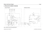


Piping and Instruments Diagram
Page 23
Operating manual LC 340.01-A.3.5/6
Current revision status: Apr 4, 2019
pressure switch. In this case the alarm message
“Refrigerant Circuit / High
Pressure”
will be displayed. For monitoring of the liquefying pressure, the high
pressure sensor (B10, B15) is used.
The compressed refrigerant is liquefied inside the air cooled condenser. Due to heat of
condensation the air will increase in temperature.
The liquid refrigerant flows through the dehumidifier and the inspection glass to the
expansion valve. The expansion valve reduces the pressure of the liquid from
condensing pressure to evaporating pressure. After expanding of the refrigerant, it
enters the evaporator as a liquid / gas mixture. Inside the evaporator the refrigerant will
be evaporated by the heat of the warm water coming from the laser modules. After this
the refrigerant vapour is drawn by compressor (M1 & M2) and the refrigeration circuit
starts again.
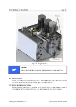
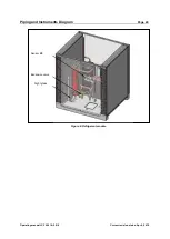
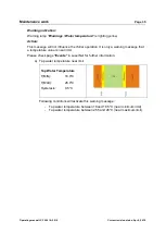
Figure 5: Refrigerant module
Condenser 1
Condenser 2
Evaporator
Compressor M1
Compressor M2
Sensor B10, (B15)
Switch A13, PS2