background image


MANUAL [

PY740025/26

]


 Subject to alteration! Version: 22.10.2018 

ipf electronic gmbh

 • Kalver Straße 25 - 27 • 58515 Lüdenscheid 

 Tel +49 2351 9365-0 • Fax +49 2351 9365-19 

 [email protected] • 

www.ipf.de

  20


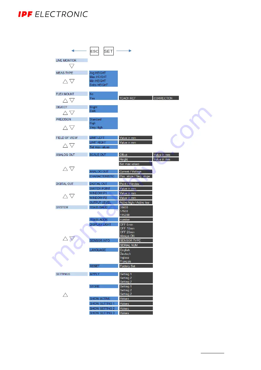
5.2  Function tree 

The menu that can be accessed via the touch panel is shown below. 


Summary of Contents for PY740025

Page 1: ...Manual for PY740025 26...

Page 2: ...Overview of control elements 17 5 2 Function tree 20 5 3 LIVE MONITOR 21 5 4 MESSTYP 24 5 5 FLEX MOUNT Function HEIGHT 25 5 6 OBJECT 30 5 7 PRECISION 30 5 8 FIELD OF VIEW 33 5 9 ANALOG OUT 35 5 10 DIG...

Page 3: ...ght section sensors It is a supplement to the mounting instructions supplied with each sensor 1 2 Intended use The PY740025 26 sensors measure heights of objects It was especially developed for easy h...

Page 4: ...gs Let s get started Connection Connect the sensor according to the connection diagram A shielded connection cable 8 pole M12 must be used When everything is correctly connected the sensor starts up L...

Page 5: ...be teached in with FLEX MOUNT The sensor can be mounted angled with up to 30 to the reference surface The sensor may be mounted at an angle inclined maximally 30 to the left or to the right of the re...

Page 6: ...AS TYPE average value maximum minimum or delta The reference surface 0 is the maximum measuring range of the sensor or if present the FLEX MOUNT teached reference surface Avg HEIGHT Distance of the av...

Page 7: ...FIELD OF VIEW The width of the measuring field can be changed with FIELD OF VIEW Separate configuration of the single points of the field LIMIT LEFT LIMIT RIGHT This function is required when there a...

Page 8: ...th affects signal noise Signal noise increases the longer the connection cable is Analog output I_OUT Noise 5 92 uA 1 Sigma 10 m cable and 680 ohm 3 59 uA 1 sigma 2m cable and 680 ohm Analog output U_...

Page 9: ...diagram Color Function Description Pin 1 WH white n c Not connected Pin 2 BN brown Vs Voltage supply 15 28 VDC Pin 3 GN green analog Analog output 4 20 mA or 0 10V Pin 4 YE yellow out Switching output...

Page 10: ...or reference levels To ensure easy alignment of the sensor during installation the surfaces defined here are available The laser beam of the sensor runs parallel to level R3 and is at a right angle to...

Page 11: ...d for teaching in the reference surface The reference surface must lie within the measuring range of the sensor The sensor may be inclined at a maximum angle of 30 to the reference surface The Maximum...

Page 12: ...ide of the sensor The sensor measures the height of objects within the measuring field With the HEIGHT function it is the end of measuring range Sde or optionally the teach in reference surface If FLE...

Page 13: ...nfo ipf de www ipf de 13 4 4 1 Blind region The region from sensor level R2 up to the start of measuring range Sdc is called the blind region i e the sensor cannot detect any objects there Objects in...

Page 14: ...ordinate system is now represented by the M and K axes The height is now measured in M direction 4 5 1 Reference point with inclined installation In the case of angled installation the zero point 0 mm...

Page 15: ...o find the reference point 0 mm This function displays the LEFT EDGE RISING the first rising edge from the left side of objects Now an object is slowly pushed toward the presumed zero point The zero p...

Page 16: ...on accessories To ensure optimal mounting the mounting bracket AP000043 is available as an accessory This bracket fits best with the ball head holder AY000143 The sensor can be aligned within the enti...

Page 17: ...If the function mode at the top is displayed on a black background the value of the bottom line can be adjusted using the UP DOWN keys and saved with SET Process successful The display background lig...

Page 18: ...Down decrease value SET OK Save new value Only in the setting menu when the top line is displayed on a black background change value 5 1 3 Locking the touch panel The keys on the control panel are loc...

Page 19: ...locked Slide over all keys from right to left Jump directly to run mode Can be used from any menu 5 1 5 LEDs on the sensor LED Lights up Flashes Yellow Out1 activated Switching output1 active Red Out...

Page 20: ...eration Version 22 10 2018 ipf electronic gmbh Kalver Stra e 25 27 58515 L denscheid Tel 49 2351 9365 0 Fax 49 2351 9365 19 info ipf de www ipf de 20 5 2 Function tree The menu that can be accessed vi...

Page 21: ...nsor LIVE MONITOR to reference surface FLEX MOUNT deactivated LIVE MONITOR to object FLEX MOUNT activated Display example LIVE MONITOR 30 mm Display example LIVE MONITOR 15 21 5mm Right Left Angle mea...

Page 22: ...ng range 1 The requirements for the object with respect to the minimum width1 and height1 must be met As soon LIVE MONITOR is active the measuring field is set to maximum and the sensors outputs are s...

Page 23: ...gle of the surface of the object relative to the axis End of measuring range 1 are displayed When moving the object into the direction of the assumed reference point until LEFT EDGE RISING displays 0m...

Page 24: ...with analog output Height 5 4 1 Avg HEIGHT Average height of the object from the reference surface 5 4 2 Max HEIGHT Maximum height of the object from the reference surface 5 4 3 Min HEIGHT Minimum he...

Page 25: ...tallation right angle to the reference surface or the object is not present the reference surface is closer to the sensor than the End of the measuring range Sde the reference surface is to be automat...

Page 26: ...unevenness a flat temporary auxiliary plate can be used for this process It is placed on the reference surface during teaching in and removed after the process This plate should be as flat as possibl...

Page 27: ...n sensor and reference surface The inclination angle of the sensor to the reference surface is too large Maximum inclination angle 30 Correct inclination of the sensor The reference surface is too une...

Page 28: ...always the basis for this Example The display lights up red during TEACH REF because of unevenness in the reference surface This reference surface does not comply with one or more conditions A 10 mm t...

Page 29: ...rs and no longer affects the measurement result NOTE As soon as FLEX MOUNT is activated SCALE OUT FIELD OF VIEW and DIGITAL OUT are reset to the standard settings SCALE OUT and FIELD OF VIEW maximum m...

Page 30: ...ur times the normal resolution12 The higher precision is set the more measuring speed is reduced response and the release time are increased The measuring frequency is not affected by using this filte...

Page 31: ...ze 2 The measurement frequency is not affected by this filter but rather the response time Moving average The output of the moving average filter is the average of all values found in the array with t...

Page 32: ...ill be output In PRECISION mode HIGH the distance has to be stable for 4 16 samples for the output to show the current value In precision mode very high the distance has to be stable for 8 128 samples...

Page 33: ...ed The modified measuring field need not be symmetrical Even a single limit e g LIMIT LEFT can be restricted LIMIT LEFT LIMIT RIGHT LIMIT RIGHT mm LIMIT LEFT mm Left Right LIMIT RIGHT mm LIMIT LEFT mm...

Page 34: ...LIMIT RIGHT Limitation of the right side of the measuring field in mm measured from the reference point 5 8 4 FIELD OF VIEW Set maximum values resets all adjustments of the measuring field to the sta...

Page 35: ...range Sde start of measuring range Sdc must be greater than 5 of the end of measuring range value OFFSET The value in mm at which the sensor should have the minimum analog output value of 0V or 4 mA i...

Page 36: ...nt to voltage 5 9 3 CHARACTERISTIC The analog characteristic curve can be inverted With a positive output slope the signal increases with an increasing measuring value For the negative slope the outpu...

Page 37: ...steresis1 for a reliable switching signal The window must be larger than 5 of the end of current measuring range 5 10 1 DIGITAL OUT Whether Pin 4 is to be operated as a threshold with a switch point o...

Page 38: ...greater than start of measuring range Sdc1 2x hysteresis1 5 10 4 WINDOW P2 Window point 2 for the WINDOW mode is selected in mm using the arrow keys The point must lie within the measuring range less...

Page 39: ...aces and output Analog signal output Current Voltage 5 11 2 DISPLAY LIGHT The display background illumination automatically switches off after the set time or remains switched on The countdown begins...

Page 40: ...settings MEAS TYPE Delta HEIGHT OBJECT Bright PRECISION Standard SCALE OUT Max values FLEX MOUNT Not activated standard installation FIELD OF VIEW Max values DIGITAL OUT Threshold end of measuring ra...

Page 41: ...ting 2 Setting 3 5 12 2 STORE The settings entered in the sensor can be stored here Three storage spaces are available Setting 1 Setting 2 Setting 3 5 12 3 SHOW SHOW displays the setting values SHOW A...

Page 42: ...recision high 6 12 m346 With filter Precision very high 70 150 m34 Without filter 45 75 m346 With filter Precision high 25 45 m346 With filter Precision very high Repeatability AVG DIST max measuring...

Page 43: ...2 8 pole Plug M12 8 pole Weight 130 g 130 g Ambient conditions PY740025 PY740026 Ambient light immunity 35 kLux 35 kLux Operating temperature 10 50 C 10 50 C Storage temperature 25 75 C 25 75 C Protec...

Page 44: ...shape elliptical focused to laser line elliptical focused to laser line Focus distance df 125 mm 350 mm Beam size exit window perpendicular parallel 2 5 mm 7 5 mm 2 2 mm 5 8 mm Beam size focus perpend...

Page 45: ...ANUAL PY740025 26 Subject to alteration Version 22 10 2018 ipf electronic gmbh Kalver Stra e 25 27 58515 L denscheid Tel 49 2351 9365 0 Fax 49 2351 9365 19 info ipf de www ipf de 45 Parallel plane df...

Page 46: ...PY740025 26 Subject to alteration Version 22 10 2018 ipf electronic gmbh Kalver Stra e 25 27 58515 L denscheid Tel 49 2351 9365 0 Fax 49 2351 9365 19 info ipf de www ipf de 46 6 1 2 Dimensions Optica...

Page 47: ...aser beam is enlarged into a line and projected to the surface of the object to be measured Using the multi lens system the reflected light from this laser line is projected onto a matrix From this ma...

Page 48: ...27 58515 L denscheid Tel 49 2351 9365 0 Fax 49 2351 9365 19 info ipf de www ipf de 48 6 2 1 qTarget The measuring field is aligned with the housing reference surfaces at the factory The beam position...

Page 49: ...ue after an object changed his position Typically it is about 2 3x measuring repetition time When the position of the object has changed during the exposure time the response time is the fastest ie ab...

Page 50: ...as a percentage of the sensing distance Without hysteresis objects could at the limit of the switching points lead to ceaseless on off switching or bouncing 6 4 2 Calculating the hysteresis The absolu...

Page 51: ...2351 9365 0 Fax 49 2351 9365 19 info ipf de www ipf de 51 6 4 3 Characteristics of the switching output at SWITCH POINT 6 4 4 Characteristics of the switching output at WINDOW High Low Hysteresis Meas...

Page 52: ...s the percentage relationship between incident and reflected light Definition of objects White object Approx 90 reflectivity Black object Approx 6 reflectivity Bright object 18 reflectivity Dark objec...

Page 53: ...Alarm output 6 5 4 Analog signal output Current or voltage output The sensor has an analog output that can send a current or voltage signal through the same pin The desired CURRENT or VOLTAGE output f...

Page 54: ...ng values can be converted from mm into the analog output signal and vice versa with the following formulas If the measuring range has been limited with SCALE OUT the new settings for Current Start of...

Page 55: ...outputs are held in the last valid state during Hold To come back to measuring mode the Sync In has to be set from High to Low The Sync in must be at least 5 s at Low to come back to the measuring mo...

Page 56: ...pf de 56 Measuring if Synch In low The sensor checks the level of the Sync In each time before it sends out the laser pulse If it is low the sensor will immediately begin the next measurement High Low...

Page 57: ...19 info ipf de www ipf de 57 Sync In Low to High If the Synch In level is High the sensor completes the actual measurement but do not start the next measurement All outputs are held Hold function Low...

Page 58: ...s to set from High to Low to bring the sensor back into the measuring mode The Sync In must be at least 5 s set to low level so that the sensor starts to measure For this first measuring cycle the res...

Page 59: ...w a defined value signal gain the alarm output and red LED on the sensor are activated Reasons for a low signal level Signal gain too small Incorrect mounting angle Insufficient light reflected from t...

Page 60: ...el 49 2351 9365 0 Fax 49 2351 9365 19 info ipf de www ipf de 60 6 5 8 Response of outputs If no object is within the measurement range the sensor will hold the last valid signal The alarm output is hi...

Page 61: ...nel 6 6 1 Function and design The display consists of a monochrome 128 x 32 pixel LCD with RGB LED background illumination The sensor can be configured using four capacitive touch operator interfaces...

Page 62: ...The standard deviation is then a measure for the unevenness of the surface All measuring points within the preset field of view are taken into consideration Remember The standard deviation is a measur...

Page 63: ...alified person Installation For mounting use only the mechanical mountings and mechanical mounting accessories intended for this product Unused outputs must not be wired In cable versions with unused...

Page 64: ...2 Do not stare into beam Class 2 lasers emit radiation in the visible portion of the spectrum 400 nm to 700 nm A short term exposure duration to 0 25 s is harmless to the eye Random short term impacts...

Page 65: ...mmediately be disconnected from the power supply and it must not be put back into operation until it has been repaired by an authorized person Non compliance with these safety instructions may result...

Page 66: ...surface with FLEX MOUNT 5 Limit the analog output using SCALE OUT OFFSET 10 mm HEIGHT 30 mm 8 1 2 Delta height measurement max min with limited measuring field left 5mm and right 20mm with inclined i...

Page 67: ...Sensor does not provide the expected measuring results Check inclination angle and work with the FLEX MOUNT mode if required teach in the new reference surface The object is not in the measuring rang...

Reviews: