Ip.Access nano3G 217A, Installation Manual
The Ip.Access nano3G 217A is a powerful and compact indoor small cell solution. For step-by-step instructions on setting up and configuring this device, make sure to download the Installation Manual for free from manualshive.com. This manual will guide you through the installation process and ensure optimal performance.
Share
Download


Reviews:
No comments
Related manuals for nano3G 217A
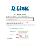
DSL-2750U
Brand: D-Link Pages: 3

3CRWE51196 - OfficeConnect Wireless Cable/DSL...
Brand: 3Com Pages: 6

Wireless Access Point 150
Brand: Hamlet Pages: 172

MK15E
Brand: SIYI Pages: 95

3000-U981-02
Brand: Emka Electronics Pages: 7

E22-230TXXS
Brand: Ebyte Pages: 27

WA2612-AGN
Brand: H3C Pages: 447

NSW-R2
Brand: Gembird Pages: 57

WAP-8111
Brand: LevelOne Pages: 31

EA6700
Brand: Linksys Pages: 124

FGMM1000
Brand: Linksys Pages: 30

BEFW11S4-AT
Brand: Linksys Pages: 31

E5600
Brand: Linksys Pages: 135

Juplink RX4-1500
Brand: Vanin Pages: 2

RF-HTN104
Brand: RocketFish Pages: 73

MiFi 500 LTE Mobile Hotspot
Brand: Novatel Pages: 9

MiFi 2
Brand: Novatel Pages: 123

2352
Brand: Novatel Pages: 108


