ION ion4 User Manual Download Page 29

2x2 Indoor & Outdoor Access Points 

Revision: A0-00 

29 


CONFIDENTIAL 


6.1.1


Connect to the Indoor Access Point 

Follow  the steps mentioned below  and connect to the indoor AP  through GUI: 

1.


Configure a computer with a 1-domain static IP address e.g. 192.168.1.1  and a subnet mask of 255.255.255.0. 

2.


For  help configuring a static IP  address on your computer,  check the instructions or online help that came 

with  that computer.\ 

3.


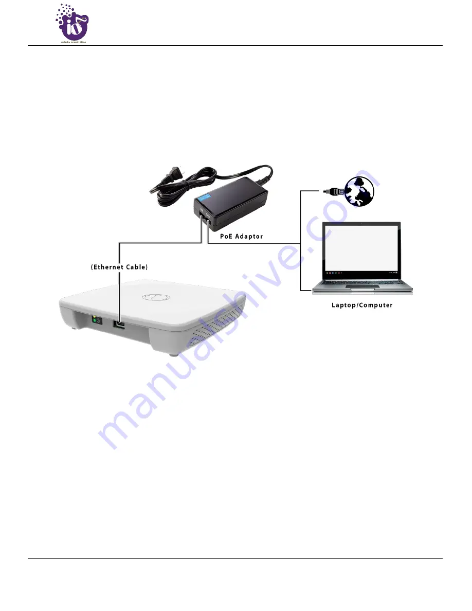
Connect the Ethernet cable to the computer. 

4.


Connect the other end of the Ethernet cable to the PoE  adaptor (Data/In port). Use the unused port (P+D/Out) 

of PoE  adaptor and connect it to the LAN + PoE port of the device. 


Figure 9: Connect to the network 

5.


Device will  be powered On. 

6.


Open a web browser and enter the “AP static IP  address” (

192.168.1.1

) in the address bar. 

7.


A login  screen will  appear. 


Summary of Contents for ion4

Page 1: ...2020 This document helps you to understand the product features configuration login and logout process of Thin and Thick Access Point This manual guides you through the installation process and the e...

Page 2: ...greement About HFCL Limited HFCL Limited delivers innovative customized and competitive products and latest solutions in the high technology telecommunications infrastructure sector thereby enabling i...

Page 3: ...2x2 Indoor Outdoor Access Points Revision A0 00 3 CONFIDENTIAL Revision History Date Rev No Description By 08 01 2020 A0 00 Initial Draft Himankush...

Page 4: ...SS POINT 22 5 1 DUAL BAND 2X2 2 INDOOR ACCESS POINT 22 5 1 1 Back Side View 22 5 2 DUAL BAND 2X2 2 OUTDOOR ACCESS POINT 24 5 2 1 Front SideView 24 5 3 BACK VIEW 25 6 INITIAL SETUP 27 6 1 DUAL BAND 2X2...

Page 5: ...NFIGURATION FOR THICK AP 62 16 1 1 Static IP configuration for thick AP 63 16 1 2 DHCPv4 client configuration for thickAP 65 16 1 3 DHCPv6 client configuration for thickAP 66 16 2 NETWORK WIRELESS RAD...

Page 6: ...INSTALLATION SETUP 94 21 1 MOUNTING OF DUAL BAND 2X2 2 INDOOR ACCESS POINT WALL AND CEILING 94 21 2 MOUNTING OF DUAL BAND 2X2 2 OUTDOOR ACCESS POINT POLE AND WALL 98 21 2 1 2x2 outdoor APmounting to t...

Page 7: ...of login screen 45 Figure 25 Basic layout of the system summary screen 46 Figure 26 Basic layout of the system software screen 47 Figure 27 Basic layout of the system hardware screen 48 Figure 28 Bas...

Page 8: ...s tool screen to check the connection status 90 Figure 62 Basic overview of the diagnostics tool screen to check the route of established connection 91 Figure 63 Basic overview of the screen to show c...

Page 9: ...able 24 List of actions to generate a backup of current device s configuration and files 55 Table 25 List of actions to upload configuration from an external file 56 Table 26 List of actions to upgrad...

Page 10: ...Table 50 List of actions to view real time traffic graphs 89 Table 51 List of actions to check the connection status 90 Table 52 List of actions to check the route of established connection 91 Table 5...

Page 11: ...he following table Document Conventions Convention Description Note Note provides information about important features or instructions This appears with a background Caution This alerts you to potenti...

Page 12: ...DHCP Dynamic Host Configuration Protocol DNS Domain Name System DSCP Differentiated Services Code Point EMS Element Management System GI Guard Interval GPS Global Positioning System GUI Graphic User...

Page 13: ...tocol OSD On Screen Display P2MP Point To Multipoint P2P Point To Point PCP Priority Code Point POE Power Over Ethernet PTZ Pan Tilt Zoom QAM Quadrature Amplitude Modulation QOS Quality Of Service RFI...

Page 14: ...ser Id UTP Unshielded Twisted Pair VAP Virtual Access Point VGA Video Graphic Adapter VLAN Virtual Local Area Network WAN Wide Area Network WDS Wireless Distribution System WIDS Wireless Intrusion Det...

Page 15: ...1 Reorient or relocate the receiving antenna 2 Increase the separation between the equipment and receiver 3 Connect the equipment into an outlet on a circuit different from that to which the receiver...

Page 16: ...r Access Points Revision A0 00 16 CONFIDENTIAL 3 1 Dual Band 2x2 2 Indoor Access Point Technical specifications of this variant are given below Figure 1 Dual Band 2x2 2 Indoor Access Point Specificati...

Page 17: ...2x2 Indoor Outdoor Access Points Revision A0 00 17 CONFIDENTIAL Figure 2 Dual Band 2x2 2 Indoor Access Point Specifications Highlights 2...

Page 18: ...s Point ion4 ion4e The Dual Band 2x2 2 outdoor Access Point has two factory fitted variants one with integrated antennas ion4 and the otherwith connectors for external antennas ion4e Technical specifi...

Page 19: ...2x2 Indoor Outdoor Access Points Revision A0 00 19 CONFIDENTIAL Figure 4 Dual Band 2x2 2 Outdoor Access Point Specifications Highlights 2...

Page 20: ...ing 1 10 100 1000 Mbps local area network device such as a hub or switch 2 The Category 5 UTP straight through Ethernet cable with RJ 45 connectorincluded in the package or one like it 3 We can power...

Page 21: ...following items 1 User can choose any of the Access Point model mentioned below a Dual Band 2x2 2 Indoor Access Point ion4i b Dual Band 2x2 2 Outdoor Access Point ion4 ion4e 2 Mounting bracket kit 3 Q...

Page 22: ...re is detailed in the table below Table 1 List of information displayed in side view of the indoor AP Callout Name Description 1 Mounting Slot This helps in the attachment of mounting bracket and indo...

Page 23: ...2x2 Indoor Outdoor Access Points Revision A0 00 23 CONFIDENTIAL 3 LAN PoE Port Used for powering up the device via PoE adaptor The same port carries the data 4 Vent Transfers the heat in the ambient...

Page 24: ...allout Name Description 1 External antenna connectors Total 2 n type antenna connectors are available for ion4e variant of 2x2 2 outdoor AP These connectors are not available in ino4 variant as the va...

Page 25: ...iew of the outdoorAP is given below Figure 7 Back view of the outdoor AP Information displayed in the above figure is detailed in the table below Table 3 List of information displayed in back view of...

Page 26: ...t to press the button It serves two functions 1 Restart Press and release the Reset button quickly 2 Restore to Factory Default Settings Press and hold the Reset button for more than five seconds 2 Sc...

Page 27: ...ccess point 1 Do not power the device during installation 2 Do not subject the device to high temperatures 3 Keep away from high voltage cables 4 Disconnect the device before cleaning it 5 Do not wipe...

Page 28: ...x2 Indoor Outdoor Access Points Revision A0 00 28 CONFIDENTIAL 6 1 Dual Band 2x2 2 Indoor Access Point Power up the device using PoE Adaptoras shown below Figure 8 Power up the device using PoE adapto...

Page 29: ...iguring a static IP address on your computer check the instructions or online help that came with that computer 3 Connect the Ethernet cable to the computer 4 Connect the otherend of the Ethernet cabl...

Page 30: ...2 Indoor Outdoor Access Points Revision A0 00 30 CONFIDENTIAL 6 2 Dual Band 2x2 2 Outdoor Access Point Power up the device using PoE Adaptoras shown below Figure 10 Power up the device using PoE adapt...

Page 31: ...iguring a static IP address on your computer check the instructions or online help that came with that computer 3 Connect the Ethernet cable to the computer 4 Connect the otherend of the Ethernet cabl...

Page 32: ...AP GUI It provides access to the users with valid login credentials only The login credentials will determine the access rights of the user A basic overview of the same is shown below Figure 12 Basic...

Page 33: ...us dropdown 2 Overview Click on Overview option 3 System summary Click on Systemsummary option 4 Hostname Displays the Hostname assigned to the respective AP in the SystemConfiguration screen 5 Model...

Page 34: ...layout of the systemsoftware is given below Figure 14 Basic layout of the system software screen Follow the steps given below to view the systemsoftware information Table 6 List of information display...

Page 35: ...he Status dropdown 2 Overview Click on Overview option 3 Hardware Click on Hardware option 4 Hardware Version Displays the current hardware version of the respective AP 5 Device Type Displays the devi...

Page 36: ...w Figure 16 Basic overview of the system admin password configuration screen Follow the steps given below and configure the systemadmin password for the AP Table 8 List of actions to configure the sys...

Page 37: ...screen is given below Figure 17 Basic overview of the reboot screen Follow the steps given below and reboot the AP Table 9 List of actions to reboot the AP Callout Name Description 1 Administration Cl...

Page 38: ...le 10 List of actions to view edit the network configuration Callout Name Description 1 Thin AP Configuration Click on Thin AP Configuration dropdown 2 Interfaces Click on Interfaces option 3 Network...

Page 39: ...IPv6 from the DHCP server Click on the Edit option in interface screen as shown in Figure 18 Basic overview of the interface configuration screen A basic overview of the network interface setup config...

Page 40: ...User can change the default IP address with an unused IP address Refer Figure 19 Basic overview of the network interface setup configuration screen to switch protocol and set the protocol to static a...

Page 41: ...n name to IP and IP to domain name 7 IPv6 Assignment Length Enable Disable the IPv6 assignment length for IPv6 address Specify the number of bits that belong to network part if enabled The prefix leng...

Page 42: ...ters Figure 21 Basic overview of DHCP client parameters for general network interface setup Follow the steps given below to provide DHCP client parameters Table 13 List of actions to provide DHCP clie...

Page 43: ...meters for general network interface setup Follow the steps given below to provide DHCPv6 client parameters Table 14 List of actions to provide DHCPv6 client parameters Callout Name Description 1 Prot...

Page 44: ...h mode from thin AP to thick AP Follow the steps given below to switch mode from thin AP to thick AP Table 15 List of actions to switch mode from thin AP to thick AP Callout Name Description 1 Switch...

Page 45: ...P GUI It provides access to the users with valid login credentials only The login credentials will determine the access rights of the user A basic overview of the same is shown below Figure 24 Basic o...

Page 46: ...temsummary is given below Figure 25 Basic layout of the system summary screen Follow the steps given below to view the systemsummary Table 17 List of information displayed in the system summary Callou...

Reviews: