


Images & Illustrations
Figure 1.
FlexJet: Lifting procedure . ....................................................................................... ix
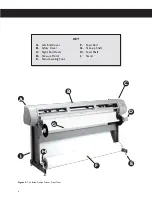
Figure 2.
The Ioline FlexJet printer front view . ................................................................... x
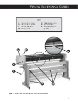
Figure 3.
The Ioline FlexJet printer rear view ...................................................................... xi
Figure 4.
The Ioline FlexJet Printer front view close-up ................................................. xii
Figure 5.
The X- and Y-axes and origin . ............................................................................... 14
Figure 6.
The serial cable and power cord sockets . ......................................................... 16
Figure 7.
PC serial ports,
COM 1
and
COM 2
. ............................................................... 16
Figure 8. FlexPlot
serial port set-up window . ................................................................. 17
Figure 9.
Workflow: using FlexPlot for output . ................................................................ 18
Figure 10.
Workflow using
FlexPlot
for file conversion and output . ........................... 18
Figure 11.
The FlexJet Keypad . ................................................................................................ 21
Figure 12.
Plot origin point location on paper . .................................................................... 22
Figure 13.
FlexJet
Control Center Main Menu
. ............................................................. 24
Figure 14.
The Hewlett-Packard 51645A (‘45’ cartridges) . ............................................... 27
Figure 15.
Ink cartridge installation . ....................................................................................... 28
Figure 16.
Installing the feed shaft . .......................................................................................... 29
Figure 17.
Installing the take-up shaft . .................................................................................... 30
Figure 18.
The correct paper feeding path on the Ioline FlexJet printer . ...................... 31
Figure 19.
Taping the paper to the take-up shaft . ................................................................ 32
Figure 20.
Positioning the pinchwheels for 72-in (183-cm) paper . .................................. 33
Figure 21.
Inserting the dancer bars . ...................................................................................... 33
Figure 22.
Location of dancer bar channels . ......................................................................... 34
Figure 23.
Manually freeing the take-up shaft . ...................................................................... 36
Figure 24.
Taping over the front take-up bar sensor . ......................................................... 38
Figure 25.
Paper path for printing to the floor . ................................................................... 38
Figure 26.
Cleaning the Drive Shaft . ....................................................................................... 39
Figure 27.
Calibration screen in
Control Center
. ........................................................... 40
Figure 28.
The Calibration box and measurements . ........................................................... 41
Figure 29.
Cartridge calibration window . .............................................................................. 42
Figure 30.
The Cartridge Alignment Box . ............................................................................. 43
Figure 31.
The Motion Adjust Box . ......................................................................................... 43
Figure 32.
The Frame Gap Box
. .........................................................................................................44
Figure 33.
Ink cartridge storage
.
. ............................................................................................ 46
Figure 34.
Factory
c
alibration sticker inside the
Service Station
................................ 50
Figure 35.
HP cartridges ink level indicator
. ...............................................................................................52
Figure 36.
Keypad LED lights . ........................................................................................................ 53


