81
Chapter 4: Repair Procedures
5.
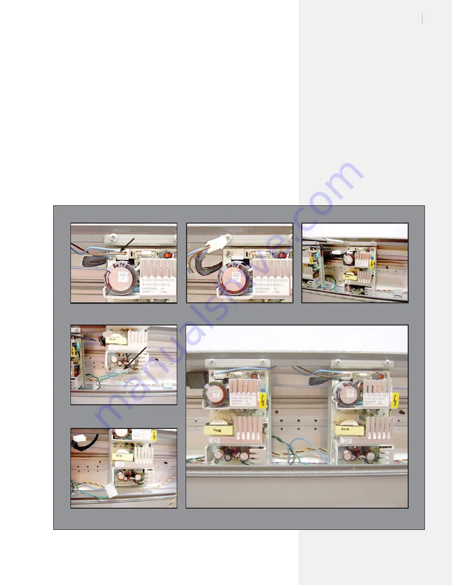
Plug the big connector into the new power supply (
Figure 46
,
photos 5 & 4).
6.
Install the new power supply into the plotter body. Make sure you
insert the bottom tab into the gap built into the body of the machine
(
Figure 46
, photo 3). Check the other power supply for an example.
7.
Plug in the small connector (
Figure 46
, photos 2 & 1).
8.
Route the wires, making certain they lay out of the way of the
bottom cover screws (
Figure 46
, photo 6).
9.
Install the bottom cover and the rotate machine back to normal
operating position. Make sure to re-install screws that hold the
machine to the stand legs.
10. Test the plotter.
11. If problems arise, contact Ioline Tech Support.
Figure 46.
Power supply replacement.
Photo 5
Photo 6
Photo 4
Photo 1
Photo 2
Photo 3
Connector
Connector
Summary of Contents for FJ Printer
Page 1: ...Service Manual Ioline FJ Printer StudioJet ...
Page 3: ...Service Manual Ioline FJ Printer StudioJet ...
Page 4: ......
Page 7: ......
Page 8: ......
Page 12: ......
Page 36: ...36 Ioline FJ Printer StudioJet Service Manual This page intentionally left blank ...
Page 61: ...61 Chapter 3 Troubleshooting Testing This page intentionally left blank ...
Page 66: ...66 Ioline FJ Printer StudioJet Service Manual This page intentionally left blank ...
Page 75: ...75 Chapter 4 Repair Procedures This page intentionally left blank ...
Page 87: ...87 Chapter 4 Repair Procedures Photo 4 Photo 5 Photo 6 ...
Page 92: ...92 Ioline FJ Printer StudioJet Service Manual This page intentionally left blank ...
Page 110: ...110 Ioline FJ Printer StudioJet Service Manual This page intentionally left blank ...


