


34
The UA262024 is a pneumatic machine and requires minimum maintenance. Bearings and
cylinders are sealed and require no lubrication. The only maintenance required is listed below.
•
Regularly clean the machine using pressured air to remove carton dust from the moving
parts.
WARNING! Always wear safety glasses when using pressured air.
•
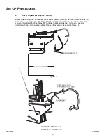
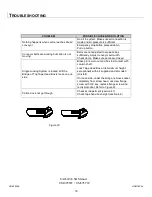
Clean or change the air filter (figure 9) when necessary. Refer to the Spare Parts section
of this manual for air filter part number.
•
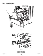
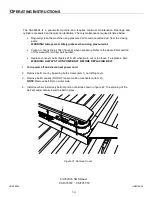
Replace conveyor belts (figures 21 & 22) when worn out or too loose. To replace a belt:
WARNING! ALWAYS TURN POWER OFF BEFORE REPLACING BELT
1.
Turn power off and disconnect power cord
.
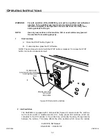
2. Remove belt cover by loosening both screws (item 1) and lifting cover.
3. Remove belt manually (DO NOT loosen tension mechanism (item 2)).
NOTE
: Remove belt first on motor side.
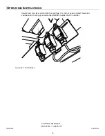
4. Install new belt. Install only bottom portion of belt as shown in figure 22. The spinning of the
belt will automatically lower the belt in place.
1
2
Figure 21 Remove Cover
UDM10008
UDM780-04
UA262024 SB Manual
UM095TW / UM595TW
O
PERATING
I
NSTRUCTIONS
Summary of Contents for IPG UA 262024 SB
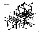
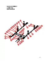
Page 40: ...4 7 2 3 5 10 9 11 12 13 15 14 8 6 19 17 16 18 1 BASE ASSEMBLY USM6104 A 1...
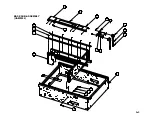
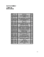
Page 42: ...4 19 13 5 10 12 18 3 8 9 1 6 22 7 2 17 16 15 14 20 BASE SUB ASSEMBLY UAM0352 A 3...
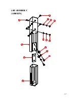
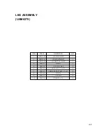
Page 46: ...A 7 LEG ASSEMBLY UAM0275 7 3 4 5 8 9 10 2 1 6 7 8 9 10...
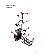
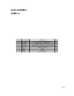
Page 48: ...A 9 GATE ASSEMBLY USM6110 2 4 3 1 8 6 7 5...
Page 54: ...2 8 16 3 19 14 5 6 10 7 17 4 11 12 13 1 9 11 12 15 USM6100 A 15...
Page 56: ...2 10 4 3 5 9 13 12 17 8 7 14 15 16 1 11 14 15 18 6 USM6101 A 17...
Page 60: ...A 21 LOCKING MECANSM USM0391 6 1 5 7 2 3 4 8...
Page 62: ...A 23 COMPRESSION GUIDE USM6109 2 5 1 4 3 6 7...
Page 64: ...A 25 KNOB CW 5mm PIN UAM0288 4 5 3 2 1...
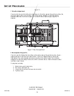
Page 75: ...A 36 ELECTRIC CONTROLS 2 1 4 8 3 6 5 7...
Page 79: ...A 40 AIR TO COLUMN ASSEMBLY 3 4 5 1 1 7 6 1 2...
Page 81: ...A 42 STOP START BOX UAM1084 STOP START BOX 5 4 7 1 10 8 2 9 3 6...
Page 87: ...A 48 SECOND E STOP INSTALLED OPTIONAL UM9003 1 3 4 7 5 6 2...
Page 89: ...A 50 SECOND E STOP BOX ASSEMBLY OPTIONAL USM8075 2 3 1 5 4...
Page 92: ...A 53 5 60 psi 3 5 PILOT 4mm TUBE AIR 8mm TUBE 3 KICKER GATE PNEUMATIC DIAGRAM...