27
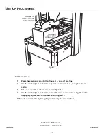
DRIVE SECTIONS
LIGHTLY SQUEEZE
CARTON
USE HANDLE
TO ADJUST BELTS
LATERALLY
DRIVE
SECTIONS
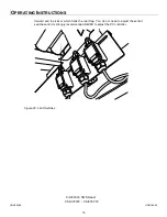
Figure 12 Width adjustment
NOTE: When width and length adjustments are completed, pull up emergency stop button
to turn machine back on.
5
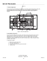
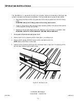
Compression Guides Adjustment (figure 13)
Compression guides (figure 13) must be adjusted to lightly squeeze the upper part of the carton.
This allows the two major flaps to contact each other and therefore insures a better seal. To
adjust, loosen the handle then slide guide laterally until pressed against box.
UDM10008
UDM780-04
UA262024 SB Manual
UM095TW / UM595TW
S
ET
-U
P
P
ROCEDURES
Summary of Contents for IPG UA 262024 SB
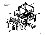
Page 40: ...4 7 2 3 5 10 9 11 12 13 15 14 8 6 19 17 16 18 1 BASE ASSEMBLY USM6104 A 1...
Page 42: ...4 19 13 5 10 12 18 3 8 9 1 6 22 7 2 17 16 15 14 20 BASE SUB ASSEMBLY UAM0352 A 3...
Page 46: ...A 7 LEG ASSEMBLY UAM0275 7 3 4 5 8 9 10 2 1 6 7 8 9 10...
Page 48: ...A 9 GATE ASSEMBLY USM6110 2 4 3 1 8 6 7 5...
Page 54: ...2 8 16 3 19 14 5 6 10 7 17 4 11 12 13 1 9 11 12 15 USM6100 A 15...
Page 56: ...2 10 4 3 5 9 13 12 17 8 7 14 15 16 1 11 14 15 18 6 USM6101 A 17...
Page 60: ...A 21 LOCKING MECANSM USM0391 6 1 5 7 2 3 4 8...
Page 62: ...A 23 COMPRESSION GUIDE USM6109 2 5 1 4 3 6 7...
Page 64: ...A 25 KNOB CW 5mm PIN UAM0288 4 5 3 2 1...
Page 75: ...A 36 ELECTRIC CONTROLS 2 1 4 8 3 6 5 7...
Page 79: ...A 40 AIR TO COLUMN ASSEMBLY 3 4 5 1 1 7 6 1 2...
Page 81: ...A 42 STOP START BOX UAM1084 STOP START BOX 5 4 7 1 10 8 2 9 3 6...
Page 87: ...A 48 SECOND E STOP INSTALLED OPTIONAL UM9003 1 3 4 7 5 6 2...
Page 89: ...A 50 SECOND E STOP BOX ASSEMBLY OPTIONAL USM8075 2 3 1 5 4...
Page 92: ...A 53 5 60 psi 3 5 PILOT 4mm TUBE AIR 8mm TUBE 3 KICKER GATE PNEUMATIC DIAGRAM...

