INSTALLATION INSTRUCTIONS
Gas Furnace: (F/G)9MVE
40
440 01 4400 03
Specifications subject to change without notice.
or tee, certified to ULC S636
from the adjacent property line
must be used. (See
The concentric vent kit currently cannot be modified to attach
an elbow to the vent portion of the rain cap. A tee attached to
the rain cap could potentially direct the flue gas plume toward
the intake air stream and contaminate the incoming combustion
air for the furnace.
Refer to
for terminations approved for
use in Alberta and Saskatchewan.
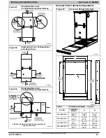
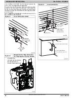
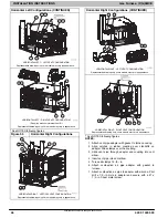
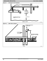
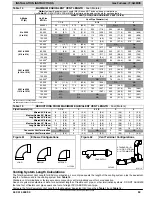
Figure 44
Tee at Termination Outlet
A13078A
OPTIONAL TERMINATION
BRACKET FOR 2-PIPE
TERMINATIONS
12-IN. (305 MM)
ABOVE ANTICIPATED
SNOW LEVEL
12 IN. (305 MM) MIN.
SEPARATION BETWEEN
BOTTOM OF COMBUSTION
AIR AND BOTTOM OF VENT.
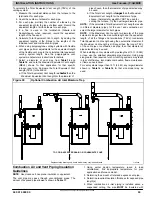
Figure 45
Sample Inlet Air Pipe Connection
for Polypropylene Venting Systems
EXAMPLE FOR
UPFLOW INSTALLATIONS.
MAY BE APPLIED TO
OTHER CONFIGURATIONS.
A12220
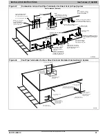
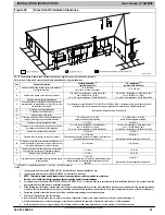
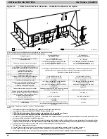
Figure 46
Vent Terminations
12 IN. (305 MM) MIN. SEPARATION
BETWEEN BOTTOM OF
COMBUSTION AIR AND
BOTTOM OF VENT.
MAINTAIN 12 IN. (305 MM)
CLEARANCE ABOVE
HIGHEST ANTICIPATED
SNOW LEVEL OR GRADE,
WHICHEVER IS GREATER.
COMBUSTION-AIR
(ELBOW PARALLEL TO WALL)
OPTIONAL
BRACKET
COUPLING
A13078B
A13078C
OVERHANG
12 IN. (305 MM) MIN. GROUND
LEVEL OR ANTICIPATED SNOW LEVEL
EXHAUST
CLEARANCE TO OVERHANG PER CODE

