International comfort products F9MVE Installation Instructions Manual Download Page 29

INSTALLATION INSTRUCTIONS

Gas Furnace: (F/G)9MVE

440 01 4400 03

29

Specifications subject to change without notice.

WARNING

!

FIRE OR EXPLOSION HAZARD

Failure to follow this warning could result in personal

injury, death, and/or property damage.
Gas valve inlet and/or inlet pipe must remain capped

until gas supply line is permanently installed to protect

the valve from moisture and debris. Also, install a sedi-

ment trap in the gas supply piping at the inlet to the

gas valve.

Gas piping must be installed in accordance with national and

local codes. Refer to current edition of NFGC in the U.S.A.

Refer to current edition of CAN/CSA B149.1 in Canada.
Installations must be made in accordance with all authorities

having jurisdiction. If possible, the gas supply line should be a

separate line running directly from meter to furnace.

NOTE

:  Use a back

up wrench on the inlet of the gas valve

when connecting the gas line to the gas valve.
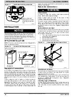
NOTICE

In the state of Massachusetts:

1. Gas supply connections MUST be performed by a li-

censed plumber or gas fitter.

2. When flexible connectors are used, the maximum

length shall not exceed 36

in. (915 mm).

3. When lever handle type manual equipment shutoff

valves are used, they shall be T

handle valves.

4. The use of copper tubing for gas piping is NOT ap-

proved by the state of Massachusetts.

Refer to 

Table 10

 for recommended gas pipe sizing. Risers

must be used to connect to furnace and to meter. Support all

gas piping with appropriate straps, hangers, etc. Use a

minimum of one hanger every 6 ft. (1.8 M). Joint compound

(pipe dope) should be applied sparingly and only to male

threads of joints. Pipe dope must be resistant to the action of

propane gas.

WARNING

!

FIRE OR EXPLOSION HAZARD

A failure to follow this warning could result in personal in-

jury, death, and/or property damage.
If local codes allow the use of a flexible gas appliance

connector, always use a new listed connector. Do not use

a connector which has previously served another gas ap-

pliance. Black iron pipe shall be installed at the furnace

gas control valve and extend a minimum of 2

in. (51 mm)

outside the furnace.

CAUTION

!

FURNACE DAMAGE HAZARD

Failure to follow this caution may result in furnace dam-

age.
Connect gas pipe to furnace using a backup wrench to

avoid damaging gas controls and burner misalignment.

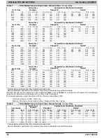
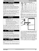
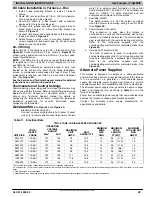
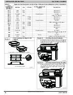
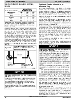
Table 10 Maximum Capacity of Pipe

NOMINAL

IRON PIPE

SIZE

IN. (MM)

INTERNAL

DIA.

IN. (MM)

LENGTH OF PIPE 

 FT (M)

10

(3.0)

20

(6.0)

30

(9.1)

40

(12.1)

50

(15.2)

1/2 (13)

0.622 (158)

175

120

97

82

73

3/4 (19)

0.824 (20.9)

360

250

200

170

151

1 (


25)

1.049 (26.6)

680

465

375

320

285

1‐1/4 (32)

1.380 (35.0)

1400

950

770

660

580

1‐1/2 (39)

1.610 (40.9)

2100

1460

1180

990

900

* Cubic ft of gas per hr for gas pressures of 0.5 psig (14-in. w.c.) or less and
a pressure drop of 0.5-in. w.c. (based on a 0.60 specific gravity gas).  Ref: 

Table 10

above,


 and 6.2 of NFPA54/ANSI Z223.1-2012.

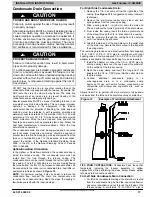
An accessible manual equipment shutoff valve MUST be

installed external to furnace casing and within 6 ft. (1.8 M) of

furnace.
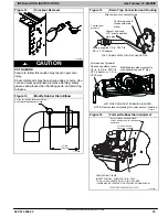
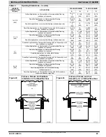
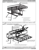
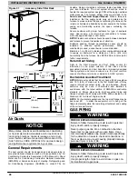
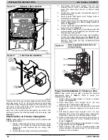
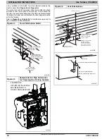
Install a sediment trap in riser leading to furnace as shown in

Figure 32

. Connect a capped nipple into lower end of tee.

Capped nipple should extend below level of furnace gas

controls. Place a ground joint union between furnace gas

control valve and exterior manual equipment gas shutoff valve.
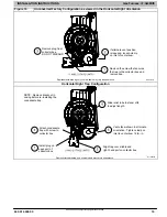
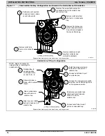
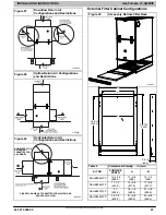
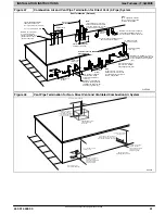
Figure 32

Typical Gas Pipe Arrangement

L10F030

A 1/8

in. (3 mm) NPT plugged tapping, accessible for test

gauge connection, MUST be installed immediately upstream of

gas supply connection to furnace and downstream of manual

equipment shutoff valve.
Piping should be pressure and leak tested in accordance with

the current addition of the NFGC in the United States, local,

and national plumbing and gas codes before the furnace has

been connected. Refer to current edition of NSCNGPIC in

Canada. After all connections have been made, purge lines

and check for leakage at furnace prior to operating furnace.

NOTE: 

The furnace gas control valve inlet pressure tap

connection is suitable to use as test gauge connection

providing test pressure DOES NOT exceed maximum 0.5 psig

(14

in. w.c.) stated on gas control valve. (See 

Figure 33

)

Summary of Contents for F9MVE

Page 1: ...owing manner Safety alert symbol When you see this symbol on the unit and in instructions or manuals be alert to the potential for personal injury TABLE OF CONTENTS SAFETY CONSIDERATIONS 3 INTRODUCTIO...

Page 2: ...grade directly in line with the exhaust vent terminal for the horizontally vented gas fueled heating appliance or equipment The sign shall read in print size no less than one half 1 2 inch in size GAS...

Page 3: ...othing and work gloves Have a fire extinguisher available Read these instructions thoroughly and follow all warnings or cautions included in literature and attached to the unit CAUTION CUT HAZARD Fail...

Page 4: ...rn air temperature of 60 F 15 C db or intermittent operation down to 55 F 15 C db such as when used with a night setback thermostat Return air temperature must not exceed 80 F 27 C db Failure to follo...

Page 5: ...to electrostatic discharge by putting the furnace the control and the person at the same elec trostatic potential 1 Disconnect all power to the furnace Multiple disconnects may be required DO NOT TOU...

Page 6: ...0401410 14 3 16 361 12 1 2 319 12 9 16 322 7 1 8 181 121 54 0401712 17 1 2 445 15 7 8 403 16 406 8 3 4 222 131 59 0601412 14 3 16 361 12 1 2 319 12 9 16 322 7 1 8 181 132 60 0601714 17 1 2 445 15 7 8...

Page 7: ...hipped in the main blower compartment See Table 2 for loose parts bag contents This furnace must be installed so the electrical components are protected from water not be installed directly on any com...

Page 8: ...airplane hangar or other building having a hazardous atmo sphere the furnace must be installed in accordance with the NFPA 54 ANSI Z223 1 2012 or CAN CSA B149 1 2010 See Figure 4 Figure 4 Installatio...

Page 9: ...de and iodide These elements can corrode heat exchangers and shorten furnace life Air contaminants are found in aerosol sprays detergents bleaches cleaning solvents salts air fresheners and other hous...

Page 10: ...sisted appliances in Btuh hr Ifan combined input of all fan assisted appliances in Btuh hr ACH air changes per hour ACH shall not exceed 0 60 The following requirements apply to the Standard Method an...

Page 11: ...ir openings shall be not less than 3 in 80 mm Table 3 Minimum Free Area Required for Each Combustion Air Opening or Duct to Outdoors FURNACE INPUT BTUH TWO HORIZONTAL DUCTS 1 SQ IN 2 000 BTUH 1 100 SQ...

Page 12: ...the potential of freezing the drain trap and drain line must be protected The use of accessory drain trap heaters electric heat tape and or RV antifreeze is recommended for these installations CAUTIO...

Page 13: ...1307 Representative drawing only some models may vary in appearance Figure 9 Unconverted Factory Configuration as viewed in the Downflow Orientation A11587LA Remove relief tube from relief port on con...

Page 14: ...nsate drainage See bottom images in Figure 10 and Figure 11 A field supplied accessory Horizontal Installation Kit trap grommet is required for all direct vent horizontal installations only The kit co...

Page 15: ...to the collector box and remove trap Representative drawing only some models may vary in appearance Horizontal Right Trap Configuration A11573LB Attach condensate trap with screw to collector box Sli...

Page 16: ...5 6 Representative drawing only some models may vary in appearance Horizontal Left Trap Configuration A11574LB Rotate elbow to desired position and torque clamp on inlet 15 lb in Slide relief tube in...

Page 17: ...e condensate drain must be routed from the trap through the furnace casing The condensate drain can be routed through the left or right side of the casing The left or right side is as you are viewing...

Page 18: ...PVC pipe by sliding a spring clamp over the open end of the grommet on the outside the furnace casing 16 Open the spring clamp and insert the long end of the adapter or the 1 2 in CPVC pipe into the o...

Page 19: ...ELBOW WITH DISCHARGE PIPE Attach elbow to condensate trap Cut formed end off condensate drain elbow Connect short end of Z pipe to modified drain elbow Factory supplied 1 2 in CPVC to 3 4 in PVC adap...

Page 20: ...asing side to attach supply air duct humidifier or other accessories All supply side accessories MUST be connected to duct external to furnace main casing Return Air Connections WARNING FIRE HAZARD A...

Page 21: ...Floor and Plenum Opening Dimensions A96283 NOTE It is recommended that the perforated supply air duct flanges be completely removed from furnace when installing the furnace on a factory supplied case...

Page 22: ...to follow this caution may result in minor property damage Local codes may require a drain pan under entire furnace and condensate trap when a condensing furnace is used in an attic application or ove...

Page 23: ...8 600 Downflow Applications on Combustible Flooring with Coil Assembly or coil box subbase not required 15 1 2 394 19 483 16 1 2 419 20 508 21 533 Upflow Applications on Combustible or Noncombustible...

Page 24: ...ire a drain pan and condensate trap when a condensing furnace is installed over a finished ceiling Figure 26 Working Platform for Attic Installation 2 in 51 mm A11154 ROLLOUT PROTECTION REQUIRED Insta...

Page 25: ...n be installed on either side of the furnace the bottom of the furnace or any combination of side and bottom of the furnace See Figure 28 Figure 31 and Figure 30 For downflow applications the filter r...

Page 26: ...shable Representative After Market Filter Media Fiberglass Pleated CFM L s 1 in 2 5 cm 1 in 2 5 cm 2 in 5 cm 1 in 2 5 cm 2 in 5 cm 800 378 0 03 9 0 05 12 0 07 18 0 17 43 0 11 28 1000 472 0 04 11 0 06...

Page 27: ...s HORIZONTAL TOP RETURN NOT PERMITTED FOR ANY MODEL SIDE RETURN AIR NOT PERMITTED FOR 2000 CFM AND ABOVE OF AIR FLOW L10F034 External Filter Cabinet Configurations Figure 30 Accessory Bottom Filter Ra...

Page 28: ...tion Ductwork passing through unconditioned space should be insulated to enhance system performance When air conditioning is used a vapor barrier is recommended Maintain a 1 in 25 mm clearance from co...

Page 29: ...h has previously served another gas ap pliance Black iron pipe shall be installed at the furnace gas control valve and extend a minimum of 2 in 51 mm outside the furnace CAUTION FURNACE DAMAGE HAZARD...

Page 30: ...to furnace When servicing controls label all wires prior to disconnecting Reconnect wires correctly Verify proper operation after servicing WARNING WARNING ELECTRICAL SHOCK HAZARD Failure to follow th...

Page 31: ...ONLY FIVE WIRE NOTE 2 NOTE 1 1 STAGE THERMOSTAT TERMINALS FIELD SUPPLIED FUSED DISCONNECT CONDENSING UNIT FURNACE COM R W GND GND FIELD 24 VOLT WIRING FIELD 115 208 230 460 VOLT WIRING FACTORY 24 VOL...

Page 32: ...6 Connect field ground wire and factory ground wire to green ground screw on J Box mounting bracket as shown in Figure 37 7 Connect field power and neutral leads to furnace power leads as shown in Fig...

Page 33: ...HUM The HUM terminal is a 24 VAC output energized when the blower is operating during a call for heat See Figure 40 3 Communication Connector This connection is used when the furnace is controlled by...

Page 34: ...E IGNITER INDUCER MOTOR CONNECTOR 115 VAC L2 NEUTRAL CONNECTIONS 115 VAC L1 LINE VOLTAGE CONNECTIONS EAC 1 TERMINAL 115 VAC 1 0 AMP MAX PL1 LOW VOLTAGE MAIN HARNESS CONNECTOR TERMINALS HARNESS CONNECT...

Page 35: ...nt t certifi s ULC S636 pour l application des composantes Royal Pipe IPEX PVC qui sont certifi es ce standard Au Canada l appr t et le ciment doivent tre du m me fabricant que le syst me d vacuation...

Page 36: ...e composed of pipe fittings cements and primers listed to ULC S636 M G DuraVent PolyPro polyproplylene venting systems are ULC S636 listed NOTE When using polypropylene venting systems all venting mat...

Page 37: ...0 for references to clearances required by National code authorities A combustion air pipe to the outdoors is not required for a single pipe vent system A 12 in 304 mm long pipe with a 2 in 50 mm Nomi...

Page 38: ...CPVC Fittings Schedule 40 F441 CPVC Pipe Schedule 40 F442 CPVC Pipe SDR F493 For CPVC Solvent Cement For CPVC F628 ABS Pipe Cellular Core DWV at Schedule 40 IPS sizes F656 For PVC Primer For PVC F891...

Page 39: ...peration could result in carbon monoxide poisoning or death For all venting configurations for this appliance and other gas appliances placed into operation for the structure provisions for adequate c...

Page 40: ...tchewan Figure 44 Tee at Termination Outlet A13078A OPTIONAL TERMINATION BRACKET FOR 2 PIPE TERMINATIONS 12 IN 305 MM ABOVE ANTICIPATED SNOW LEVEL 12 IN 305 MM MIN SEPARATION BETWEEN BOTTOM OF COMBUST...

Page 41: ...grade whichever is greater Typ At least 36 in 914mm At least 36 in 914mm Side wall termination of less than 12 in 305mm above highest snow level Maintain 12 in 305mm min Clear ance above highest anti...

Page 42: ...er of the intake air pipe with EITHER a removable cap attached to a 6 inch long pipe connected to the tee or the External vent Trap Kit to help prevent contaminants from entering the furnace See Figur...

Page 43: ...be used for venting the furnace Try the next larger diameter pipe NOTE If the calculated Total Equivalent Vent Lengths results in different diameter pipes for the vent and combustion air select the la...

Page 44: ...hese instructions Install the Vent and Combustion Air Pipes With the furnace installed in the required position remove the desired knockouts from the casing It will be necessary to remove one knockout...

Page 45: ...ing only some models may vary in appearance DOWNFLOW LEFT VENT CONFIGURATION See NOTES following figures Downflow Configurations CONTINUED A11312 Representative drawing only some models may vary in ap...

Page 46: ...pearance Horizontal Right Configurations CONTINUED HORIZONTAL RIGHT LEFT VENT CONFIGURATION Representative drawing only some models may vary in appearance HORIZONTAL RIGHT RIGHT VENT CONFIGURATION Rep...

Page 47: ...manently cementing any joint 1 Working from furnace to outside cut pipe to required length s 2 De burr inside and outside of pipe 3 Chamfer outside edge of pipe for better distribution of primer and c...

Page 48: ...e same manufacturer WARNING CARBON MONOXIDE POISONING HAZARD Failure to follow this warning could result in personal injury or death DO NOT use cement to join polypropylene venting systems Follow the...

Page 49: ...ittings Clean and cement using same procedures as used for system piping DO NOT CEMENT POLYPROPYLENE FITTINGS Two Pipe and Single Pipe Vent Termination NOTE Follow the instructions of the vent termina...

Page 50: ...pace Vent Termination 3 76 mm 12 305 mm Pipe hangar VentilatedCombustion Air intake termination in crawl space Ventilated Combustion Air intake pipe CRAWL SPACE L11F016A Figure 58 Attic Vent Terminati...

Page 51: ...y 12 in 305 mm Permitted only if veranda porch deck or balcony is fully open on a minimum of two sides beneath the floor See Note 4 Manufacturer s Recommendation See Notes 3 8 M Clearance to each side...

Page 52: ...ance under a veranda porch deck or balcony 12 in 305 mm Permitted only if veranda porch deck or balcony is fully open on a minimum of two sides beneath the floor See Note 4 Manufacturer s Recommendati...

Page 53: ...1 150 45 7 202 61 6 224 68 3 100 000 NA 17 5 2 94 28 7 205 62 5 229 69 8 120 000 NA NA NA 83 25 3 217 66 1 140 0004 NA NA NA 69 21 0 146 44 5 See notes at end of Venting Tables See Table 16 for altit...

Page 54: ...ludes FOR EACH PIPE 100 feet 30 M of vent pipe 95 feet 28 M of combustion air inlet pipe 3 90 long radius elbows and a polypropylene concentric vent kit Also includes 20 feet 6 1 M of flexible polypro...

Page 55: ...NA NA NA 62 18 9 175 53 3 140 0004 NA NA NA 32 9 8 63 19 2 8001 to 9000 2438 to 2743 40 000 10 3 0 121 36 9 130 39 6 NA NA 60 000 7 2 1 82 25 0 152 46 3 168 51 2 NA 80 000 NA 35 10 7 111 33 8 148 45...

Page 56: ...11 6 N A 80 000 20 10 Ft 20 0 64 0 64 0 56 0 47 0 20 0 70 0 173 0 150 0 125 0 20 0 70 0 175 0 177 0 147 0 M 6 1 19 5 19 5 17 1 14 3 6 1 21 3 52 7 45 7 38 1 6 1 21 3 53 3 53 9 44 8 0 20 Ft 20 0 32 0 3...

Reviews: