D-0134090-A – 2022/11
VisualEyes™ - Instructions for Use - EN
Page
26
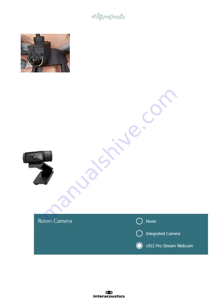
Figure 2.6-9: Calibration laser on the EyeSeeCam goggle.
Hardware setup:
1. Connect the USB mini-B connector to the connector on the EyeSeeCam camera.
2. Connect the other end of the USB cable to the supplied USB hub. Ensure that the hub is powered
through the external power supply.
3. Mount the camera on the goggle using the spherical ball-and-socket joint.
4. Mount the calibration laser on the bridge of the goggle.
5. Register the EyeSeeCam goggle as ”EyeSeeCam” in the the VisualEyes™ software, following the
instructions in section 2.8:
Hardware registration and licensing
6. Ensure that the calibration laser is in horizontal/vertical alignment, and adjust if necessary.
2.6.2 External room camera
All VisualEyes™ systems are delivered with an external room camera. This can be used to record the
environment, for example to see how the patient was positioned during measurements, or to record patient
interviews. The room recordings are synchronized with the eye recordings.
Figure 2.6-10: Sample picture of an external room camera
Hardware setup:
1. Place the camera on a location where the environment can be properly recorded.
2. Connect the USB cable to a USB port on the computer or on the USB hub.
3. Navigate to
Configuration > System Default Settings > Input
, and select the connected camera in the
list under
Room Camera
.
Figure 2.6-11: Selection of room camera under System Default Settings > Input


