• Click “New” to create a new entry for editing to the table (temporary until “Submit” is clicked).
• Click “Add” to add the new entry to the table (temporary until “Submit” is clicked).
• Click “Modify” to save changes to an existing entry (temporary until “Submit” is clicked).
• Click “Remove” to remove a selected entry (temporary until “Submit” is clicked).
• Click “Attach All” to select all ports for a selected entry (temporary until “Submit” is clicked).
• Click “detach All” to unselect all ports for a selected entry (temporary until “Submit” is clicked).
• Click “Submit” to save changes to the RAM memory of the switch.
• Click “Refresh” to display current settings of the switch for viewing the effect of changes.
WarNiNg:
Clicking “Submit” only configures the switch hardware and saves the
settings to RAM memory. Such changes will be lost if the switch is powered off. To
save changes permanently in the switch’s Flash memory, click on “Save Configuration”
(listed at the bottom of the Configuration Menu). Once the “Save Configuration” screen displays,
click “Save” to store all configurations permanently in the Flash memory.
2.2.2 system
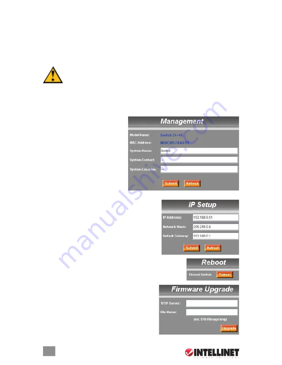
System on the Config Menu presents Management, IP Setup, Reboot and Firmware Upgrade.
2.2.2.1 Management
Model Name:
The product name is listed.
MAC Address:
The switch’s MAC
address is listed.
System Name:
The user-assigned name
to identify the system (editable).
System Contact:
enter info as desired.
System Location:
enter info as desired.
Click “Submit” to commit the settings.
Click “Refresh” to display current switch
settings. To eventually make all changes
permanent in Flash memory, click on
“Save Configuration” (listed at the bottom of the Configuration Menu) and click “Save.”
2.2.2.2 IP Setup
IP Address:
This is the IP address for the switch.
Network Mask:
This is the network mask for this network.
Default Gateway:
This is the default gateway of the network.
Click “Submit” to commit the settings. Click “Refresh” to
display current switch settings. To eventually make all
changes permanent in Flash memory, click on “Save
Configuration” (listed at the bottom of the Configuration
Menu) and click “Save.”
2.2.2.3 Reboot
Clicking “Reboot” (rebooting the system) stops the network traffic and
terminates the Web interface connection.
2.2.2.4 Firmware Upgrade
Enter the TFTP server IP address and firmware filename
(e.g., enter “192.168.1.155” and “3112Single-v10.img”).
Click “Upgrade” to update the switch’s firmware from the
TFTP server. Click “Upload” to load the assigned
firmware to the switch, then reboot the system after a
successful firmware update. You’ll need to log in to the
Web interface again.
14
WEb MANAgEMENT
Summary of Contents for 523868
Page 1: ...Managed Layer 3 Access Switch user manual Model 523868 INT 523868 UM 0807 01...
Page 2: ......
Page 52: ...NOTES 52...
Page 53: ...NOTES 53...
Page 54: ...NOTES 54...
Page 55: ...NOTES 55...


