background image

4

MDrivePlus CANopen R020507

Device Control

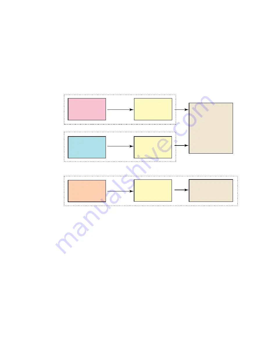
The starting and stopping of the drive and several mode specific commands are executed by the state machine. 

Modes of Operation

The operation mode defines the behavior of the drive. The following modes are defined in this profile:

Homing Mode

This chapter describes the various methods to find a home position (also: reference point, datum, zero point).

Profile Position Mode

The positioning of the drive is defined in this mode. Speed, position and acceleration can be limited and profiled moves using 
a Trajectory Generator are possible as well.

Profile Velocity Mode

The Profile Velocity Mode is used to control the velocity of the drive with no special regard of the position. It supplies limit 
functions and trajectory generation.

Homing Function

Position Function

Velocity Function

Trajectory

Generator

Trajectory

Generator

Trajectory

Generator

Position Control 

Loop

Velocity Control 

Loop

Homing Mode (Section X)

Profile Position Mode (Section X)

Profile Velocity Mode (Section X)

Figure 1.3: Functional Architecture

Summary of Contents for MDrive DSP-402

Page 1: ...Excellence in Motion DSP 402 APPLICATION GUIDE TM TM CANopen TM FORCE DRIVE CANopen...

Page 2: ...ems Inc s general policy does not recommend the use of its products in life support or aircraft applications wherein a failure or malfunction of the product may directly threaten life or injury Per In...

Page 3: ...1601h Entry Description Mapping Parameters 12 Consumer PDO3 RPDO3 1402h Object Description 13 Consumer PDO3 RPDO3 1402h Entry Description 13 1602h Object Description Mapping Parameters 13 1602h Entry...

Page 4: ...resent Point Target 23 Object Description 23 Entry Description 23 Object 2212h Position Final Point Target 23 Object Description 23 Entry Description 23 Object 5001h Configuration 23 Entry Description...

Page 5: ...iption 39 Entry Description 39 Object 6086h Motion Profile Type 40 Object Description 40 Entry Description 40 Section 7 Homing Mode 41 General Information 41 Input Data Description 41 Output Data Desc...

Page 6: ...lword 6040h of Profile Velocity Mode 51 Statusword 6041h of Profile Velocity Mode 51 Object 606Ch Velocity Actual Value 51 Object Description 51 Entry Description 51 Object 60FFh Target Velocity 52 En...

Page 7: ...ative Limit and Index Pulse 43 Figure 7 4 Homing on the Positive Limit and Index Pulse 44 Figure 7 5 Homing on the Positive Home Switch and Index Pulse 44 Figure 7 7 Homing on the Home Switch and Inde...

Page 8: ...vi This Page Intentionally Left Blank...

Page 9: ...402 Implementation Section 2 Manufacturer Specific Objects Section 3 Accessing the MDrivePlus CANopen Section 4 Device Control Section 5 Modes of Operation Section 6 Profile Position Section 7 Homing...

Page 10: ...MDrivePlus CANopen R020507 Page Intentionally Left Blank...

Page 11: ...Figure 1 1 The Figure is for reference only please refer to the CAN 2 0B Specification MDrivePlus Architecture CAN Node Application Layer and Communications Profile DS 301 Drive Profile DSP 402 Devic...

Page 12: ...ing of the drive is defined in this mode Speed position and acceleration can be limited and profiled moves using a Trajectory Generator are possible as well Profile Velocity Mode The Profile Velocity...

Page 13: ...DrivePlus node on a CANopen network Entries within the Object Dictionary are addressed using 16 bit Indexes In the case of simple variables VAR the index refer ences the value of the variable directly...

Page 14: ...he types consist of one or more bytes One byte consists of 8 bits Bit 0 to 7 Bit 0 is the LSB Least Significant Bit A byte can also be depicted hexadecimally 0x00 0xff If a data type consists of n byt...

Page 15: ...of the Index will be expressed as a Integer or Unsigned Default The range of the Index will be expressed as a Integer or Unsigned Sub Indexes An object may have a number of Sub Indexes which further d...

Page 16: ...MDrivePlus CANopen R020507 Page Intentionally Left Blank...

Page 17: ...ads from entries or writes to entries of the Object Dictionary The SDO transport protocol al lows transmitting objects of any size The first byte of the first segment contains the necessary flow contr...

Page 18: ...o 1600 02h 607Ah 4 Desired Axis Position in Hex 6 Set 1600h 00 to 2 Max Sub Indexes 1600h 00 2h 7 Turn On RPDO1 1400h 00 0000 01C0h 8 Place MDrive in Profile Position Mode 6060h 00 1 1h 9 Place MDrive...

Page 19: ...l R W 0d 1600h Object Description Mapping Parameters Index Name Object Code Data Type Category 1600h Receive PDO1 Mapping Record PDO Mapping Mandatory 1600h Entry Description Mapping Parameters Sub In...

Page 20: ...Object Description Mapping Parameters Index Name Object Code Data Type Category 1601h Receive PDO2 Mapping Record PDO Mapping Conditional if 1401h is implemented 1601h Entry Description Mapping Param...

Page 21: ...1601h Receive PDO3 Mapping Record PDO Mapping Conditional if 1402h is implemented 1602h Entry Description Mapping Parameters Sub Index Description Category Access Value Range Default 00h Highest Supp...

Page 22: ...R W 6041 0010h 02h 2nd Application Object Optional R W Mfg Specific 03h 3rd Application Object Optional R W Mfg Specific 04h 4th Application Object Optional R W Mfg Specific 05h 5th Application Object...

Page 23: ...th Application Object Optional R W Mfg Specific 07h 7th Application Object Optional R W Mfg Specific 08h 8th Application Object Optional R W Mfg Specific Producer PDO3 TPDO3 1802h Object Description I...

Page 24: ...Object Mandatory R W 6041 0010h 02h 2nd Application Object Optional R W 6064 0010h 03h 3rd Application Object Optional R W Mfg Specific 04h 4th Application Object Optional R W Mfg Specific 05h 5th App...

Page 25: ...8 Entry Description Sub Index Description Category Access PDO Mapping Value Range Default 01h ConFigure I O as Output Mandatory R W No 0x00 0xFF 0x00 1 Output 0 Input 02h ConFigure I O as Sourcing Ma...

Page 26: ...0x00 0xFF 0x00 1 Selects I O as the Positive Limit 03h ConFigure I O as Negative Limit Mandatory R W No 0x00 0xFF 0x00 1 Selects I O as the Negative Limit Object 2004h Input Filter Mask Config The In...

Page 27: ...Optional R W No 00h FFh 20h 07h Input Filter Mask Optional R W No 00h FFh 40h Object 2006h Input Filter Time ms Object Description Index 2006h Name Input Filter Time Object Code VAR Data Type Unsigne...

Page 28: ...ftware Limits as Hardware Limits Object Description Index 2020h Name Software Limits as Hardware Object Code VAR Data Type Unsigned 8 Entry Description Sub Index Description Category Access PDO Mappin...

Page 29: ...served Reserved 1 Reserved Reserved Reserved Reserved Encoder Enabled Trip Out Reserved Reserved Default 0 0 0 0 0 0 0 0 Example 0 0 0 0 1 1 0 0 Object 2032h Clock Options Object Description Index 203...

Page 30: ...s R W S PDO Mapping No Range 1 100 Default 25 Run Current By Device 2204h MDrivePlus All MForce MicroDrive Amps RMS MForce PowerDrive Amps RMS 10 MDrive Range 0 To 100 Actual Current Not required as M...

Page 31: ...rrent Object 2211h Position Present Point Target Object Description Index 2211h Name Position Present Point Target Object Code VAR Data Type Integer 32 Entry Description Access R PDO Mapping No Range...

Page 32: ...following object is set at the factory and is not user configurable It can be read by the user in the event that the con tained data is needed for technical or application support Object Description I...

Page 33: ...ady To Switch On High Voltage may be applied to the drive The drive parameters may be changed The drive function is disabled Switched On High Voltage has been applied to the drive The Power Amplifier...

Page 34: ...d Event Disable Voltage command received from host Action The power section is switched off immediately and the motor is free to rotate if unbraked 10 Switched On Switch On Disabled Event Disable Volt...

Page 35: ...Machine States Transitions Block Diagram Notes On State Transitions Commands directing a change in state are processed completely and the new state achieved before additional state change commands are...

Page 36: ...Enable Operation Bit 3 Quick Stop Bit 2 Enable Voltage Bit 1 Switch On Bit 0 Shutdown 0 X 1 1 0 2 6 8 Switch On 0 0 1 1 1 3 Switch On 0 1 1 1 1 3 Disable Voltage 0 X X 0 X 7 9 10 12 Quick Stop 0 X 0...

Page 37: ...n 0 1 X 0 0 0 1 Switched On 0 1 X 0 0 1 1 Operation Enabled 0 1 X 0 1 1 1 Quick Stop Active 0 0 X 0 1 1 1 Fault Reaction Active 0 X X 1 1 1 1 Fault 0 X X 0 0 0 0 X Irrelevant Bit State Bit 4 shown for...

Page 38: ...age If the bit remote is reset then the drive is in local mode and will not execute the command message The drive may transmit messages containing valid actual values like a position_actual_value depe...

Page 39: ...tion mode The IMS MDrivePlus CANopen supports the following Modes of Operation Profile Position Profile Velocity Homing Mode Object Description Index 6060h Name Mode of Operation Object Code VAR Data...

Page 40: ...ration Display shows the current mode of operation The meaning of the returned value corresponds to that of the Modes of Operation option code index 6060h Object Description Index 6061h Name Mode of O...

Page 41: ...0 Profile Position Velocity Profile Velocity Profile Torque Reserved Homing Interpolated Position Cyclic Sync Position Cyclic Sync Velocity Cyclic Sync Torque Reserved MFG Specific 1 1 1 0 0 0 0 0 0 0...

Page 42: ...34 MDrivePlus CANopen R020507 Page Intentionally Left Blank...

Page 43: ...ly For the IMS MDrivePlus CANopen the following values apply target_position microsteps profile_velocity microsteps sec end_velocity microsteps sec profile_acceleration microsteps sec2 profile_deceler...

Page 44: ...apezoidal moves are used as this is the only motion_profile_type the MDrivePlus CANopen supports If the bit change_set_immediately is 0 shaded area in Figure 3 2 a single set point is expected by the...

Page 45: ...xt target_position X2 V2 V1 T0 T1 T2 Velocity Time Second target_position given immediate response target_position reached Figure 6 4 Set of Setpoints Move on a Move 6040h Bit 5 1 Controlword 6040h of...

Page 46: ...ion profile mode using the MDrivePlus CANopen parameters such as velocity acceleration deceleration motion profile type etc The target position is given in terms of 51 200 units per motor shaft revolu...

Page 47: ...ntry Description Access rw PDO Mapping Possible Range Integer 32 Default n a Object 6083h Profile Acceleration Profile Acceleration is given in steps sec2 Object Description Index 6083h Name Profile A...

Page 48: ...elect the type of motion profile used to perform a move The MDrivePlus CANopen is fixed at Value 0 Linear Ramp Trapezoidal Profile Object Description Index 6086h Name Motion Profile Type Object Code V...

Page 49: ...tion in the use of these speeds as the response to the signals may be Dependent upon the hardware used Output Data Description There is no output data except for those bits in the statusword which re...

Page 50: ...en the zero position for the application and the machine home position found during homing During homing the machine home position is found and once the homing is completed the zero position is offset...

Page 51: ...pping Possible Range Integer 8 Default 0 Data Description Value Description 128 1 Manufacturer Specific 0 No Homing Operation Required 1 35 Homing Methods 1 through 35 See Functional Description 36 12...

Page 52: ...is sited so that the direction of movement must reverse during homing the point at which the reversal takes place is anywhere after a change of state of the home switch Methods 5 and 6 Homing on the...

Page 53: ...methods 11 to 14 the initial direction of movement is to the left except if the home switch is active at the start of the motion In this case the initial direction of motion is Dependent on the edge b...

Page 54: ...Methods 17 to 30 Homing without an Index Pulse These methods are similar to methods 1 to 14 except that the home position is not dependent on the index pulse but only Dependent on the relevant home o...

Page 55: ...e current position is taken to be the home position Homing Speeds 6099h Object Description Index 6099h Name Homing Speeds Object Code VAR Data Type Unsigned 32 Entry Description Sub Index Description...

Page 56: ...48 MDrivePlus CANopen R020507 Page Intentionally Left Blank...

Page 57: ...ition Demand Value Object Code VAR Data Type Integer 32 Entry Description Access r PDO Mapping n a Range Integer 32 Default n a Object 6063h Position Actual Value Internal This object shall provide th...

Page 58: ...DO Mapping n a Range Unsigned 32 Default n a Object 6066h Following Error Timeout This object shall indicate the conFigure d time for a following error condition after that the bit 13 of the statuswor...

Page 59: ...alt 0 Target position not reached Halt 1 Axis decelerating 1 Halt 0 Target position reached Halt 1 Axis velocity is 0 12 Speed 0 Speed is not equal to 0 1 Speed is equal 0 13 Max Slippage Error 0 Maxi...

Page 60: ...60F8h Maximum Slippage This object shall indicate the conFigure d maximal slippage of an asynchronous motor When the max slippage has been reached the corresponding bit 13 max slippage error in the st...

Page 61: ...iption Index 60FDh Name Digital Inputs Object Code VAR Data Type Unsigned 32 Entry Description Access ro PDO Mapping n a Range Unsigned 32 Default n a LSB MSB 31 16 23 15 4 3 2 1 0 Negative Limit Swit...

Page 62: ...tion Sub Index Description Category Access PDO Mapping Value Range Default 00h Highest Supported Sub Index Mandatory C No 02h Mfg Specific 01h Physical Outputs Mandatory R W Possible Unsigned 32 0000...

Page 63: ...HE PRODUCT This Limited Warranty shall be void if the Customer fails to comply with all of the terms set forth in this Limited Warranty This Limited Warranty is the sole warranty offered by IMS with r...

Page 64: ...France Phone 33 4 7256 5113 Fax 33 4 7838 1537 E mail bmartinez imshome com Germany Sales Phone 49 35205 4587 8 Fax 49 35205 4587 9 E mail hruhland imshome com Germany UK Technical Support Phone 49 7...

Reviews: