background image

v240C – Marine Satellite Communication System

148

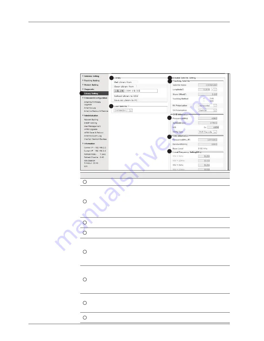
Library Setting

No.

Item

Description 


1

Library Setting

Display and set the satellite library information.


2

Library

- Get Library from ACU: Obtain satellite information installed in the 
   ACU.
- Open Library from PC: open the satellite library file from the
  supplied Intellian CD or from the external hard drive/PC.
  (File format: *.ilf)
- Upload Library to ACU: upload the satellite library file to ACU.
- Save as Library to PC: save the current library setting to the PC.


3

Load Satellite

Select the satellite that you wish to track and press Load Satellite 
button to load the selected satellite.


4

Selected
Satellite Setting

Displays selected satellite information.


5

Tracking
Satellite

- Satellite: displays satellite name.
- Longitude: displays satellite orbit position.
- Skew offset: displays Skew offset.
- Tracking method: displays current tracking MENU (DVB/NBD)
- RX polarization: displays current RX polarization.
- TX polarization: displays current TX polarization.


6

DVB Information

- Displays DVB tracking MENU's tracking information.
- Frequency: displays tracking frequency.
- Symbol rate: displays symbol rate.
- NID: displays network ID.
- Verify type: displays verification type (AGC only, DVB lock, DVB 
decode, DSS decode)


7

NBD Information

Displays NBD tracking MENU's tracking information.
- Frequency: displays tracking frequency.
- Bandwidth: displays detection bandwidth.


8

Local Frequency
Setting (MHz)

Displays LNB local frequency (MHz) and voltage.

1

3

4

5

6

7

8

2

Summary of Contents for v240C

Page 1: ...Marine Satellite Communication Antenna System v240C Installation and Operation Manual...

Page 2: ......

Page 3: ...llectual property rights covering subject matter in this document Except as expressly provided in any written license agreement from Intellian the furnishing of this document does not give you any lic...

Page 4: ...INDEX...

Page 5: ...U 65 Introduction 66 Normal Menu 67 Setup Menu 71 Installation Settings 72 Antenna Settings 74 Satellite Settings 86 System Settings 93 Aptus 101 Introduction to Aptus 102 Software Installation 103 PC...

Page 6: ...v240C Marine Satellite Communication System 6...

Page 7: ...7 INTRODUCTION Introduction to Intellian v240C Features of Intellian v240C Basic System Configurations INTRODUCTION...

Page 8: ...nage Each unit comes preloaded with a ready to use client customized library that can be conveniently tailored further via PC software also included with the unit and firmware updates can be done enti...

Page 9: ...hange the settings of Intellian antenna system wirelessly using laptops smartphones or any kind of wireless devices Antenna log data and firmware upgrade through USB The ACU of v240C now automatically...

Page 10: ...connected with all of the provided components properly as shown in the figure below Refer to next chapter Installation in this manual for more detailed connection instructions Basic System Configurat...

Page 11: ...ion of Antenna Installation Site Configure Radiation Hazard Blockage Zones System Cables Power Requirement Tools Required for Installation Antenna Installation Unpacking the Wooden Crate Antenna Dimen...

Page 12: ...for the optimum search and reception of satellite signal Mechanical Unit manipulates the antenna to receive the optimal satellite signal regardless of the movement of the vessel Control Unit controls...

Page 13: ...s of the ACU are as follows Monitor the antenna status Change the target satellite Set up the user environment Set the current GPS information Set satellite information Move antenna manually Built in...

Page 14: ...PC D Sub 9 pin Male Connector 2 ACU N to F Adaptor 1 N Male to F Female Adaptor USB Flash Drive 1 User Manual 1 RF Hazard Sticker 1 Radiation Safety Distance Label Self Tapping Screw 5 M4 x 16L Bolt K...

Page 15: ...UMAX 9 M12 Hex Bolt 235 M6x35L Bolt for Radome Assembly Hex Bolt 55 M6x35L Bolt for Radome Base Assembly Flat Washer 580 M6 18 Washer Nut for Radome Radome Base Assembly Spring Washer 290 M6 Hex Bolt...

Page 16: ...v240C Marine Satellite Communication System 16 Tools required for Installation...

Page 17: ...17 INSTALLING THE ANTENNA Box Adaptor Sillicon Gun Sillicon 10 19 24mm Box Socket Monkey Wrench Long Socket Ratchet Handle Impact Drill...

Page 18: ...lowing points into consideration 1 All cables need to be well clamped and protected from physical damage and exposure to heat and humidity 2 Remember to observe the minimum bend radius of the selected...

Page 19: ...tallation Confirmation of size prior to installation Confirm the height and diameter of the bottom surface of the antenna before installing it The space must be sufficient for installing the antenna u...

Page 20: ...nsmit equipment may be hazardous to persons close to the above deck unit Ensure safety of personnel who work on the system Duringtransmission ensuretokeeptheminimumsafetydistance Therecommended minimu...

Page 21: ...e following instruction needs to be followed in order to execute the proper removal of the system from its original packaging To secure the safe installation process please make sure to have enough sp...

Page 22: ...adome Package On the picture shown on left boxed side of wooden assembly needs to be dismantled There are nails on the circled parts of the packaging The packaing will be taken apart using an Impact D...

Page 23: ...23 INSTALLING THE ANTENNA Remove the wall as shown left D...

Page 24: ...lite Communication System 24 3 Dismantling The Radome panels Cut all the ties around the radome panels Carefully remove the radome panels After complete removal of radome panels packaging should be as...

Page 25: ...ectly above the packaging should be seen as shown left Now prepare to remove the Base frame by removing bolts from wooden crate floor and base frame legs B C 4 Removal of Radome Panel Supports and Bas...

Page 26: ...Base Frame Now prepare to attach buckles to base frame in order to lift the base frame from wooden crate As shown left all buckle ropes should be applied to all 4 joints of base frame After applying b...

Page 27: ...INSTALLING THE ANTENNA Attachment of buckle ropes and lifting ropes should look as shown left A 4000mm Lifting strap B Buckle Rope Base Frame ready to be lifted up should be seen as shown left D E F A...

Page 28: ...tach buckles to base frame in order to lift the base frame from wooden crate Secure the strap tightly as shown left for a safe removal Make sure that the center of Base Frame is located right below of...

Page 29: ...LLING THE ANTENNA Very slowly lift up the base frame and watch as the base frame lifts up to prevent big interference with wooden crate Lower the base frame onto the floor and remove the lifting assem...

Page 30: ...ackage and Free the CL Arm Dismantle the wooden assembly of the antenna package using an impact drill Remove the vinyl layer from the antenna Under the wooden support there is a post laying Remove the...

Page 31: ...ke out all brackets on the rear of the CL ARM by removing M5 flat head bolt 8EA using an impact drill F Locate the 2 brackets on the rear of the CL Arm D Take out 8mm pieces 8EA securing the brackets...

Page 32: ...v240C Marine Satellite Communication System 32 Locate the M12 Hex Bolts 4EA on both sides of the EL Arm Remove the total 4 M12 Hex Bolts securing each side of the EL Arm A B 8 Remove Bolts on EL Arm...

Page 33: ...33 INSTALLING THE ANTENNA Locate the M16 bolts that secure the pedestal assembly to the crate Remove the M16 Hex Bolts and Nuts using a wrench as shown left A B 9 Free the Upper Antenna...

Page 34: ...Communication System 34 10 Assembly of Base Frame and Post With the direction of the bow in mind place the post on the top of the base frame Check to confirm the orientation of the pedestal support w...

Page 35: ...apply Loctite 262 to the bolts to securely tighten the assembly Now for the final time please make sure that the post is attached in accordance with correct bow direction Power switch unit mount plate...

Page 36: ...11 Detachment of the Upper Antenna In order to attach lifting straps the following steps must be performed This is the initial position of the EL Arm fixture bolt The initial position should be moved...

Page 37: ...section B Lifting straps cannot be attached the CL arm in this position As shown in Section C when the tap is moved lifting strap can be attached to the CL arm 4000mm Lifting straps should be hooked o...

Page 38: ...v240C Marine Satellite Communication System 38 Securely hook the lifting straps as shown On the both side of the CL arm Securely hook the lifting straps as shown On the both side of the CL arm G H...

Page 39: ...39 INSTALLING THE ANTENNA Hook the straps to the crane as slowly lift up the system as shown Do not place the antenna onto the post just yet Follow the next steps in section 12 securing Cables I...

Page 40: ...tem 40 Locate the power and RF cables as shown Pull the cables through the center of the pedestal middle plate as shown on left The cables need to be inserted through the center of the pedestal suppor...

Page 41: ...41 INSTALLING THE ANTENNA Place the cables through the center hole of the Post as shown in C Cables should come out of the bottom of the post as shown left D E...

Page 42: ...and RF cables as shown Insert the 3 M16 x 40 bolts to secure the antenna assembly to the pedestal Make sure to apply Loctite 262 to securely tighten the assembly The system should be mounted so the AZ...

Page 43: ...Sikaflex 291 to side of radome panels before applying bolts B C Now assemble the lower radome panels M6x35L bolts are used for the connection between panels and M6x30L bolts are used for connection be...

Page 44: ...v240C Marine Satellite Communication System 44 Apply the bolts as shown right with corresponding sizes Make sure to apply bolt and nut as shown It is recommended that the max torque be 15Nm D E...

Page 45: ...e Make sure to tighten all the joints before proceeding to next step plus make sure to clean out the silicon mess to give a smooth finish Direction of the hatch should be the exactly opposite of Bow d...

Page 46: ...unication System 46 Apply the silicon between the radome panels from the outside Make sure to clean out the silicon for smooth finish Finished lower radome should look as shown A B C 16 Applying Silli...

Page 47: ...e assembly of the upper radome panels should now be completed using the M6 x 35 bolts supplied Apply silicon Sikaflex 291 to side of radome panels before fastening bolts Make sure to apply bolt and nu...

Page 48: ...ssembly of Upper Radome Cap and Finishing Assemble 4 upper radome panels as shown left You are now ready to install the radome cap Fix the cap in place with a layer of silicon and loosely fasten the M...

Page 49: ...d be installed to finish the assembly The final section is completed with a person inside the radome so a provision needs to be made so they can be released by lifting the completed dome At this point...

Page 50: ...e Satellite Communication System 50 19 Applying Silicon to Upper Radome Panels Apply the silicon from the outside between the radome panels Remove excess sealant and smooth to complete the radome top...

Page 51: ...sets of M6x35 Hex Bolts and Nuts that should be applied to 4 locations of the upper radome The assembly shown on right should be constructed on each of 4 locations Connect the lifting strap to the ra...

Page 52: ...er radome on top of the lower radome assembly Once placed onto the lower half fasten with the supplied nuts and bolts Then clean off any excess silicon Enter the radome hatch and take out 2 brackets u...

Page 53: ...G F G F G F G Green Green Neutral Neutral Neutral Neutral Air Conditioner 15A Neutral Neutral Neutral Yellow Blue Blue Air Conditioner 100 240V 50 60 Hz 15A SMPS Light Yellow Yellow Green Blue Blue Bl...

Page 54: ...v240C Marine Satellite Communication System 54...

Page 55: ...9 Rack Mount Type Table Mount Type ACU Dimensions Selection of ACU Installation Site Ship Gyro Connection Connecting the System with a Ship s Gyro Connecting the System without a Ship s Gyro WiFi Blue...

Page 56: ...talled Connect the cables to the rear of the ACU Table Mount Type The ACU should be installed using the two supplied Table Mounting Brackets which allow for a top or bottom mounting configuration Usin...

Page 57: ...installed below deck in a location that is Dry cool and ventilated The front panel should be easily accessible to the user ACU Dimensions Dimension of ACU 48 5 cm 19 1 46 6 cm 18 4 3 2 cm 1 3 13 0 cm...

Page 58: ...EA 0183 and NMEA 2000 gyro types If the ship s gyrocompass output uses something different than a NMEA 0183 or NMEA 2000 a separate purchase of a gyro converter is required NMEA 0183 Gyro Compass Inte...

Page 59: ...satellite is decoded by the antenna Search 3 The antenna will search for the target satellite by turning its azimuth angle directly to the position calculated using the ship s heading input and lock o...

Page 60: ...ng up the PC AP MENU to access Wi Fi Aptus Web Confirmation Set Up the ACU to access Wi Fi Turn on the switch on the back of the ACU and 30 seconds after enabling the power supply confirm if a red lig...

Page 61: ...92 168 1 223 PC IP 192 168 1 222 Subnet Mask 255 255 255 0 Gateway 192 168 1 223 Case 2 If iARM Module s IP is unknown The iARM module s secondary IP is 10 10 10 1 PC IP 10 10 10 2 Subnet Mask 255 255...

Page 62: ...nfirm the logo and version data by accessing http 192 168 1 223 Login by entering the ID Password listed below Username intellian Default Password 12345678 Default When you login make sure that all th...

Page 63: ...Signal Pin Signal 1 GND 6 GPS OUT 2 GPS OUT 7 Modem_SIGNAL_IN 3 Modem_LOCK 8 Modem_CTRL2 4 Modem_CTRL1 TX MUTE 9 GPS IN 5 GPS IN ACU Console Port D Sub 9 pin Female D Sub 9 pin Male connector Supplied...

Page 64: ...reads 5 3 4 1 2 Sockets Connector Threads Pin Signal 1 Shield 2 NET S power supply positive V 3 NET C power supply common V 4 NET H CAN H 5 NET L CAN L Pin Signal 1 Shield 2 NET S power supply positiv...

Page 65: ...nual Search Setup Antenna LNB pol Angle Search Parameters Setting Antenna Parameters Setup Block Zone Diagnosis Procedures Satellite Settings Load Satellite Edit Satellite Information Add Satellite In...

Page 66: ...ber Keys Power Switch MENU Touch key Function OK KEY Enter next step or menu MENU Enter SETUP MENU BACK In SETUP MENU returns to previous menu or option or saves the adjusted settings In NORMAL MENU r...

Page 67: ...LIZE SAT POSITION INTELLIAN v240 5 The antenna returns to the target satellite position SEARCH1 125 0E ASIA6AH SIG 101 AZ 150 7 150 7 EL 45 3 SK 02 0 6 The antenna is searching for the target satellit...

Page 68: ...Narrow band detection mode for TRACKING SIGNAL is chosen to be used and AGC will be displayed when DVB mode of TRACKING SIGNAL is chosen to be used The symbol will be only displayed when the satellite...

Page 69: ...firmware version ACU part number ACU serial number ACU Pol Controller firmware version Press BACK Key to return to the first page of the antenna current status 7 Press RIGHT arrow key to display the U...

Page 70: ...LOG DATA COPY LOG DATA TO USB 30 display the copy progress in percentages NOT ENOUGH SPACE IN USB USB occupies no memory space CHECK USB CONNECTION the USB flash drive is not connected 9 Press RIGHT a...

Page 71: ...unction is activated press MENU key or when Fn Menu is activated press FUNCTION key the ENTER PASSWORD Menu will be displayed ENTER PASSWORD 2 If the key pad lock function is on enter the password bef...

Page 72: ...Press UP and DOWN arrow keys to increase or decrease the value Or press NUMBER keys to set the desired value directly Press OK key to set the parameter GYRO TYPE BOW OFFSET NMEA 000 5 Set the ship s G...

Page 73: ...arch 3 MODEM TYPE LOCAL FREQ IDIRECT I O 05150MHz LOADING DO NOT TURN OFF 8 Setting is being loaded to the system The ACU will restart the system automatically after uploading the setting DO NOT TURN...

Page 74: ...nually peaking AZIMUTH 0 360 and ELEVATION 0 90 angle for best signal level Press NUMBER key to change the STEP SIZE Range 0 1 99 9 Press LEFT and RIGHT arrow keys to increase or decrease the azimuth...

Page 75: ...K key to run the selected operation CALIBRATION or MANUAL ADJUST Select MANUAL ADJUST to control LNB pol angle manually If the control board skew potentiometer or belt is replaced select CALIBRATION t...

Page 76: ...SET POL ANGLE SEARCH PARAM SET PARAMETERS 3 Press DOWN arrow keys to move cursor to SEARH PARAM and press OK key to it SEARCH WAIT TIME INCREMENT STEP 030 0 50 4 Set SEARCH WAIT TIME and INCREMENT STE...

Page 77: ...d search in the azimuth CCW direction and search up 0 5 down 0 5 with a total of 6 3 in elevation The search cycle will repeat until the antenna receives the lock signal from the Modem or the DVB tran...

Page 78: ...nu A search pattern will automatically be initiated when AGC SIG falls below the current threshold setting this indicates that satellite signal has been lost The search patterns are conducted in a two...

Page 79: ...nna system These parameters should only be changed by an authorized service technician Improper setting of these parameters will render your system inoperable DETECT DVB TRACKING DVB 040 020 5 Set DET...

Page 80: ...t the parameter you wish to edit and press BACK key again to save or abort and return to the main display Noise Level Detect Level Tracking Level TRACKING DVB NDB Peak Level DETECT DVB NDB BOW OFFSET...

Page 81: ...ION items OPERATION SAVE save and execute the current settings IDLE ON OFF the motor brakes will be released while IDLE Menu is ON The antenna will restart automatically if IDLE menu is re set from ON...

Page 82: ...t ON to setup the block zone for ZONE 1 Press OK key to use ZONE 1 BLOCK and set the zone 1 block range Press BACK key to select the parameter you wish to edit and press the BACK key again to save or...

Page 83: ...ame as ZONE 1 BLOCK Press OK key to set ZONE 2 BLOCK and set next parameter SAVE YES NO 6 Press LEFT arrow key to move cursor to YES and press OK key to save and execute the current settings Or press...

Page 84: ...ss OK key to enter ANTENNA menu BLOCK ZONE DIAGNOSTIC 3 Press arrow keys to move cursor to DIAGNOSTIC menu and press OK key to enter it DIAGNOSTIC COMMUNICATION FULL TEST READY 4 Press UP and DOWN arr...

Page 85: ...s tested CODE 108 The tilt sensor is tested CODE 109 The sensor box motor is tested CODE 110 The LNB NBD is tested CODE 111 The LNB pol motor is tested CODE 112 The sub reflector is tested Skip for v...

Page 86: ...rsor to SATELLITE and press OK key to enter it LOAD SAT EDIT SAT ADD SAT CHECK NID 3 Press OK key to enter LOAD SAT menu LOAD SATELLITE 1 C ASIA6AH 125 0E 4 Press UP and DOWN arrow keys to select sate...

Page 87: ...M INSTALLATION 2 Press RIGHT arrow key to move cursor to SATELLITE and press OK key to enter it LOAD SAT EDIT SAT ADD SAT CHECK NID 3 Press RIGHT arrow key and OK key to enter EDIT SAT menu EDIT SATEL...

Page 88: ...se DVB Decode for satellite tracking DSS Decode use DSS Decode for satellite tracking SELECT LOCAL TRACK SIGNAL 05150MHZ NBD 7 Set SELECT LOCAL frequency and TRACKING SIGNAL Press LEFT and RIGHT arrow...

Page 89: ...NUMBER keys to set the desired value directly Press OK key to set the parameter NBD FREQ BANDWIDTH 1070 000MHz 01 000MHz 10 Set NBD IF FREQUENCY and BANDWIDTH when NBD Narrow Band Detection MENU of T...

Page 90: ...ONGITUDE and satellite NAME DVB VERIFY SKEW OFFSET DVB DECODE 00 0 5 Edit the satellite DVB VERIFY and SKEW OFFSET DVB VERIFY will be only activated and applied when DVB mode of TRACKING SIGNAL is cho...

Page 91: ...NID 00000MHz 00000KSps 0X0000 8 Set DVB FREQUENCY SYMBOL RATE and NID when DVB MENU of TRACKING SIGNAL is chosen to be used 45 000 is the maximum allowed symbol rate value NID network ID range is from...

Page 92: ...HECK NID Menu CHECK NID F 4080 S 27500 0X0888 PRESS OK RECEIVED NID 0X0000 4 CHECK NID is to verify the NID Network ID of the current tracking transponder Press OK key to verify the NID 0 x 0000 only...

Page 93: ...SET LOCAL SET LOCATION MODEM PORT MANAGEMENT 3 Press OK key to enter SET LOCAL menu to set the LNB local frequency LOCAL FREQ 05150MHz SAVE YES NO 5 Press LEFT arrow key to move cursor to YES and pre...

Page 94: ...rn 1 or 3 will be initiated according to which GYRO TYPE is selected and the existence of the gyro input Set the BAUD RATE as 4800 9600 19200 or 38400 according to your device A search pattern 1 will...

Page 95: ...Press the OK key to set the parameter HEADING 000 0 6 Entry of ship s heading is not required when your system is connected to a NMEA 0813 or NMEA2000 Heading Gyrocompass output Ensure that the suppor...

Page 96: ...IATOR if the antenna is connected to the Intellian Dual VSAT Mediator NOTE USE MEDIATOR must be disabled if there is no MEDIATOR connected to the ACU Improper setting of this parameter will cause your...

Page 97: ...t to a Modem ROSS ROSS Open Antenna Management ROAM protocol is developed by Comtech EF Data Cooperation to offer common management interface for Comtech EF Data s Roaming Oceanic Satellite Server ROS...

Page 98: ...searching or is mis pointed 0 5 from peak satellite position TX MUTE ACTIVE item will only be activated when PROTOCOL is set as I O CONSOLE SAVE YES NO Use EXT LOCK USE EXT LOCK EXT LOCK ACTIVE YES L...

Page 99: ...o set the parameter and the processing message will be displayed SELECT PROCESS TYPE BACKUP USER DATA To backup the antenna settings set by user RESTORE USER DATA To restore the antenna by using the b...

Page 100: ...INTELLIAN DEVICE 3 Press arrow keys to move cursor to KEY LOCK menu and press OK key to enter it NOTE INTELLIAN DEVICE menu is not operated in this ACU KEY LOCK UNLOCK P W ON 1590 4 Press UP and DOWN...

Page 101: ...are Installation PC to ACU Communication Setup Starting Aptus Establishing a data communication Toolbar Menus System Property Status Dashboard Work View Tabs Antenna Basic Info Antenna Advanced Info S...

Page 102: ...e minimum PC hardware and software requirements to install and run Aptus are as below Hardware Hardware Requirements CPU Intel Pentium 4 or higher Memory 512MB or higher Video Card DirectX9 0 or highe...

Page 103: ...l Aptus directly onto your computer laptop The InstallShield Wizard will guide you through the program setup process The installation routine provides an icon on the desktop Click the icon to start th...

Page 104: ...rting Aptus Double click the Aptus desktop icon then Communication Window appears to establish the data communication between your PC and the ACU Select options of connection method to access your ACU...

Page 105: ...ress Factory default 192 168 2 1 5 Enter in the ACU s port number Factory default 4002 6 Click the Connect button then the Authentication window will appear 7 Login by using the username and password...

Page 106: ...is available 2 Current software version information is displayed 3 It notifies new software version information 4 When you click the start button File downloading message is displayed while downloadin...

Page 107: ...ntenna is restarted 1 1 2 2 3 4 5 6 Backup Backups the antenna information to ACU or PC Select To ACU to backup the antenna information to ACU The backup file file format ibf will be stored on the ACU...

Page 108: ...saved to the list under User Layout menu When changes are made to the current layout select Save current layout option The current layout will be saved with changes To remove a layout select Delete l...

Page 109: ...by ticking the checkbox next to it At any time data communication channel can be re established between Serial and Network connection Selecting Comm Button will display Communication Window to connec...

Page 110: ...view options ACU Log Manager displays the antenna log data in calendar view which is downloadable directly to a desired path Setting Help 6 Report provides e mail contact to Intellian technical suppor...

Page 111: ...nection status and the gray is disconnection status How to set up Spectrum Analyzer 1 Spectrum Analyzer Function Display that a spectrum analyzer measures an input Rx signal frequency within the full...

Page 112: ...the resolution number 100 200 300 or 600 in drop down list These numbers facilitate a zoom in zoom out feature Then click the Set button to apply the adjusted value The adjusted value is shown at the...

Page 113: ...follow these steps 1 Adjust Center Freq to the desired value e g 1824 MHz 2 Adjust Span value to the desired value e g 300 MHz 3 Adjust Resolution to the desired value e g 300 4 Click the Set button...

Page 114: ...h 1 pattern will automatically be initiated when the ship s heading input does not exist or if it fails The search cycle will repeat until the antenna receives the lock signal from the Modem or until...

Page 115: ...e next to the Blockage will show Gray If the antenna pointed outside the blockage zone the circle next to the Blockage will show Blue Pointing displays whether or not the antenna is pointing to the ta...

Page 116: ...than the tracking level threshold the signal level bar will display Orange color and the antenna will stay in searching mode NOTE If the signal level is not higher than the tracking threshold decreas...

Page 117: ...117 OPERATING THE ACU Diagnostic Error Report The square button next to the Diagnostic Error Report turns red when the system receives an error Click the button to see a Diagnostic Report 7...

Page 118: ...nter the Setup MENU by clicking Setup icon 2 Tick the checkbox next to the Set button to modify the settings 3 Enter the desired value then press the Set button to save the settings 1 Antenna Basic In...

Page 119: ...ian recommends you check with your service provider or satellite operator to get the satellite skew offset value and input it in Satellite Work Tab rather than resetting the mechanical skew offset dir...

Page 120: ...long term pointing drift error Tilt bias must be adjusted when the antenna control board or sensor box is replaced If the bubble on the button level located on the sensor box is not centered follow th...

Page 121: ...and cross level motor brakes while the antenna is in Setup MENU Step 3 Check whether or not the bubble is located at the center of the button level If not move it to the center by following the previ...

Page 122: ...age zones can be programmed Once the blockage zone is created a blue shad ing area will be displayed in the Antenna UI view on the right Threshold Settings DVB Detect Level displays and sets signal de...

Page 123: ...current position NOTE Based on the satellite EIRP footprint and the size of the antenna you may not be able to track all the satellites visible in 180 arc Tracking Information of Current Satellite di...

Page 124: ...les Add Satellite Edit Satellite and Delete Satellite buttons Eutelsat Select ON when the antenna is tracking an Eutelsat satellite With this option enabled a defined skew angle for each Eutelsat sate...

Page 125: ...lect Graph Item Start Stop Save the chosen item is saved within the data log The data log which stores the information displayed in the graphs can be later used for a service technician to find out a...

Page 126: ...Antenna Advanced View Tab Show Param shows the current antenna parameters Check NID verifies the NID network ID of the current tracking tran sponder Press the NID button to obtain the NID only if the...

Page 127: ...tes the test result as Pass while Red indicates the result as Fail Yellow indicates the test has been skipped Serial Comm tests the data communication between the antenna and the ACU Motor AZ tests th...

Page 128: ...cted to the ACU Improper setting of this parameter will cause your ACU s Modem interface to work incorrectly Select Modem selects your Modem type for loading pre configuration settings If the ABS auto...

Page 129: ...o vides a logic input through a 5V HIGH or 0 V LOW current to the ACU to identify when the system is on the correct satellite Modem Lock will only be activated when Modem protocol is set as I O Consol...

Page 130: ...b is separated from the rest of your Work View Tabs again click and hold the left mouse button on the Work View Tab s header to display a cross shaped Navigator icon While holding the mouse button bri...

Page 131: ...on of the Work View layout Move the selected Work View Tab to the left position of the Work View layout Move the selected Work View Tab to the center position of the Work View layout Move the selected...

Page 132: ...g them out right click the mouse button on a desired Tab header and select New Horizontal Tab Group or New Vertical Tab Group option Selecting New Horizontal Tab Group will separate a selected Tab fro...

Page 133: ...Zoom Out Bar zooms in and out to expand and reduce the View to the desired size The zoom changes in 10 increments View Switch Button displays a list of the current views in a list Choosing one of thes...

Page 134: ...v240C Marine Satellite Communication System 134...

Page 135: ...setting Antenna Position Parameters Tracking setting Modem Setting Diagnostic Library Setting Firmware Configuration Antenna Firmware Upgrade Antenna Log Antenna Backup Restore Administration Network...

Page 136: ...e activities such as operating firmware upgrades tracking parameters resets and system diagnostic How to access Aptus Web 1 Connect an Ethernet Cable between your PC and the Management Ethernet Port 2...

Page 137: ...NG The Control Monitoring menu will be switched to the Monitoring Only menu in the following cases If Aptus is connected using TCP IP Communication while Aptus Web Control is in use If Control Monitor...

Page 138: ...tracking the target satellite 3 TX Enable TX Disable Displays whether or not the antenna is able to transmit the data 4 Restart Restart the antenna system 5 Setup Enter SETUP MENU 6 Save Sat Save cur...

Page 139: ...PS Displays current GPS information Longitude East West Latitude North South 4 Heading Device Displays current Heading Device NONE NMEA NMEA 2000 Ground test If the ship s gyro input is other than NME...

Page 140: ...d shows BLUE dot only if all of the factors listed below shows BLUE dot Exception If Use TX Mute is set as NO the TX function will be enabled regardless of which factor listed below shows gray dot or...

Page 141: ...st and ship s heading information 5 Blockage Set the antenna s blockage zones up to 5 by azimuth and elevation sectors AZ START is where the relative azimuth starts and AZ END is where the relative az...

Page 142: ...y current antenna position Relative Azimuth display antenna relative AZ angle Absolute Azimuth display antenna absolute AZ angle Elevation display antenna elevation angle LNB Pol Angle display LNB pol...

Page 143: ...NBD tracking MENU is chosen to be used TX Enable Threshold display set TX enable threshold Wait time set the time out for automat ic initiation of a search after the signal level drops below the pre d...

Page 144: ...display and set Skew offset Tracking Method display and set current tracking MENU DVB NBD RX Polarization display and set current RX polarization TX Polarization display and set current TX polarizatio...

Page 145: ...d Modem Port is to select a proper data communication port on the ACU to interface with the satellite Modem RS232 422 Ethernet Modem Protocol is to select a proper communication pro tocol on the ACU t...

Page 146: ...test the LNB pol motor Antenna Power test the antenna power ACU Power test the ACU power 3 Graph Select to view a graph of AZ Absolute AZ Relative EL and Heading data of the antenna A Month display a...

Page 147: ...ect Enabling Auto Connect and rebooting the ACU will save connection data and will auto connect once ACU is powered on next time Status Displays iDirect modem status Last Update Date Displays last upd...

Page 148: ...cted Satellite Setting Displays selected satellite information 5 Tracking Satellite Satellite displays satellite name Longitude displays satellite orbit position Skew offset displays Skew offset Track...

Page 149: ...and click Start Upload button With Auto Upgrade option selected click Check button to check automatically if there is new firmware available from the server Note Auto Upgrade is available only when t...

Page 150: ...by clicking Check button 2 Click on Start Upload button to transfer the Firmware package file fwp to E2S Ethernet to serial module In Auto Upgrade mode click Upgrade button once new firmware file is d...

Page 151: ...is completed 7 Click on Back to main page to go out of the screen To verify the upgraded firmware version go to Dash Board Software Information Upgrade complete page NOTE To roll back to the previous...

Page 152: ...Firmware Log Display log information of firmware upgrade 1 2 3 4 5 Log Downloade procedures 1 Select Start Download button 2 To run Java applications you must have Java Runtime Environment JRE versio...

Page 153: ...on for the past one day 5 Select Download to download the log file to the target directory according to the selected log period NOTE You can choose to Enable or Disable the GPS tracking function Liabi...

Page 154: ...m Description 1 Antenna Backup Restore Enter backup Restore page Setup MENU is required 2 Target Backup antenna information to ACU PC or restore antenna by using the saved information from ACU PC 3 Ba...

Page 155: ...signed to NAT Routing Enable Disable NAT routing TCP Modem Protocol Port TCP port number for modem protocols using TCP as transport UDP Modem Protocol Port UDP port number for modem protocols using UD...

Page 156: ...tes and associates with an access point or IBSS cell Password WiFi access password Max Stations Setting max stations 5 Network Service Configuration Telnet Service Enable or disable telnet login suppo...

Page 157: ...n mode 5 V3 Authentication Encoding Set SNMP V3 authentication encoding 6 V3 Username Set the V3 username and password of the SNMP Agent The password is at least 8 character string 7 V3 Private Encodi...

Page 158: ...ID Enter your current login ID user name and new login ID Click the Submit button to validate the changes that are made to the login ID Change Password Enter your current login password and new login...

Page 159: ...loaded In Auto Upgrade mode click Upgrade button once new firmware file is detected 3 It ll inform you that the firmware is being uploaded 1 3 4 2 No Item Description 1 iARM Upgrade Upgrade the firmwa...

Page 160: ...ot turn off the ACU power if the firmware upgrade page is displayed 5 It ll take around 2 minutes to complete the firmware upgrade Once the upgrade is completed the system will reboot automatically Fi...

Page 161: ...Save settings to the ACU and reboot or reboot the system without saving 2 Save Reboot Save the modified settings and reboot the system Click Save Reboot button 3 Reboot without Saving Reboot the syste...

Page 162: ...me Login ID and IP 2 Query Filter Set the Log message option Severity Set urgency level Category Set target that caused the message Time Frame Set time limit that you want to show Sorting Order Sortin...

Page 163: ...ntellian network devices then you can browse the various information of the device IP Address IP address of the device to be monitored HTTP HTTPS SSH Set port number These port numbers will be matched...

Page 164: ...time Environment JRE version 6 0 and above installed in your PC laptop If JRE has not been installed in your PC laptop you ll get the below message box Click Run button to install it through online or...

Page 165: ...PPENDIX NOTE The JRE installation guide may vary depending on the operating system installed in your PC laptop Method 1 Online method for downloading and installing http www java com en download manua...

Page 166: ...e Download dialog box appears prompting you to run or save the down load file Click Save to download the file to your local system Tip Save the file to a known location on your computer for example to...

Page 167: ...irm the last steps of the installation process click Close button on the last dialog 9 This will complete Java installation process NOTE You may need to restart close and re open your browser to enabl...

Page 168: ...r supply the antenna will confirm if it is operating normally 2 In order to utilize the antenna s Bluetooth function access to Aptus and click Use Bluetooth button in the Antenna Basic Info section Th...

Page 169: ...hile the Bluetooth device is getting ready to be used you can choose to add a bluetooth device if you right click on the Bluetooth icon Methods of setting up Bluetooth within your notebook can differ...

Page 170: ...pending on each user and if you click next then the wizard will search for a Bluetooth device The window for adding a bluetooth device may differ by the type of Operating System being used 5 Pair the...

Page 171: ...ge Do this by entering 1234 within the Secu rity Code box In a case where the OS or the Bluetooth program has a Skip button available then instead of entering a pairing code press the Skip button to g...

Page 172: ...u go to a Generic Serial Service page which applies to some OS Sys tems select the Generic Serial Service and click Next Click Finish to complete Bluetooth setup tasks 8 Go to your toolbar and right c...

Page 173: ...173 APPENDIX 10 Go to the Hardware tab and check your COM Port Number 11 Excute the PC Program NOTE Remember the COM Port Number for step 12...

Page 174: ...ssign the correct COM Port step 10 and check the Connect box 13 Press the Get Ant Info button to confirm if the antenna s data within the PC Program is functioning normally End of Bluetooth Setup To D...

Page 175: ...r 185cm 72 8 Base Frame Material Method Steel Welding Weight 245kg 551 Ibs Antenna Assembly Specification Diameter 2 4m 94 5 Weight 305kg 672 Ibs Rx Frequency Standard 3 625 GHz 4 2 GHz Gain 37 7 dBi...

Page 176: ...racter Graphic VFD Module PC Interface RS232C 57600 bps 8 N 1 USB Modem Interface Ethernet port RS232C I O ports RF Interface Antenna RX N Type Modem RX F Type Gyrocompass Interface NMEA 2000 NMEA 018...

Page 177: ...he warranty period In case of failure to present the purchase receipt the warranty period will begin 30 days after the manufacturing production date of the product purchased Any product which is prove...

Reviews: