background image

86

Using AptusNX

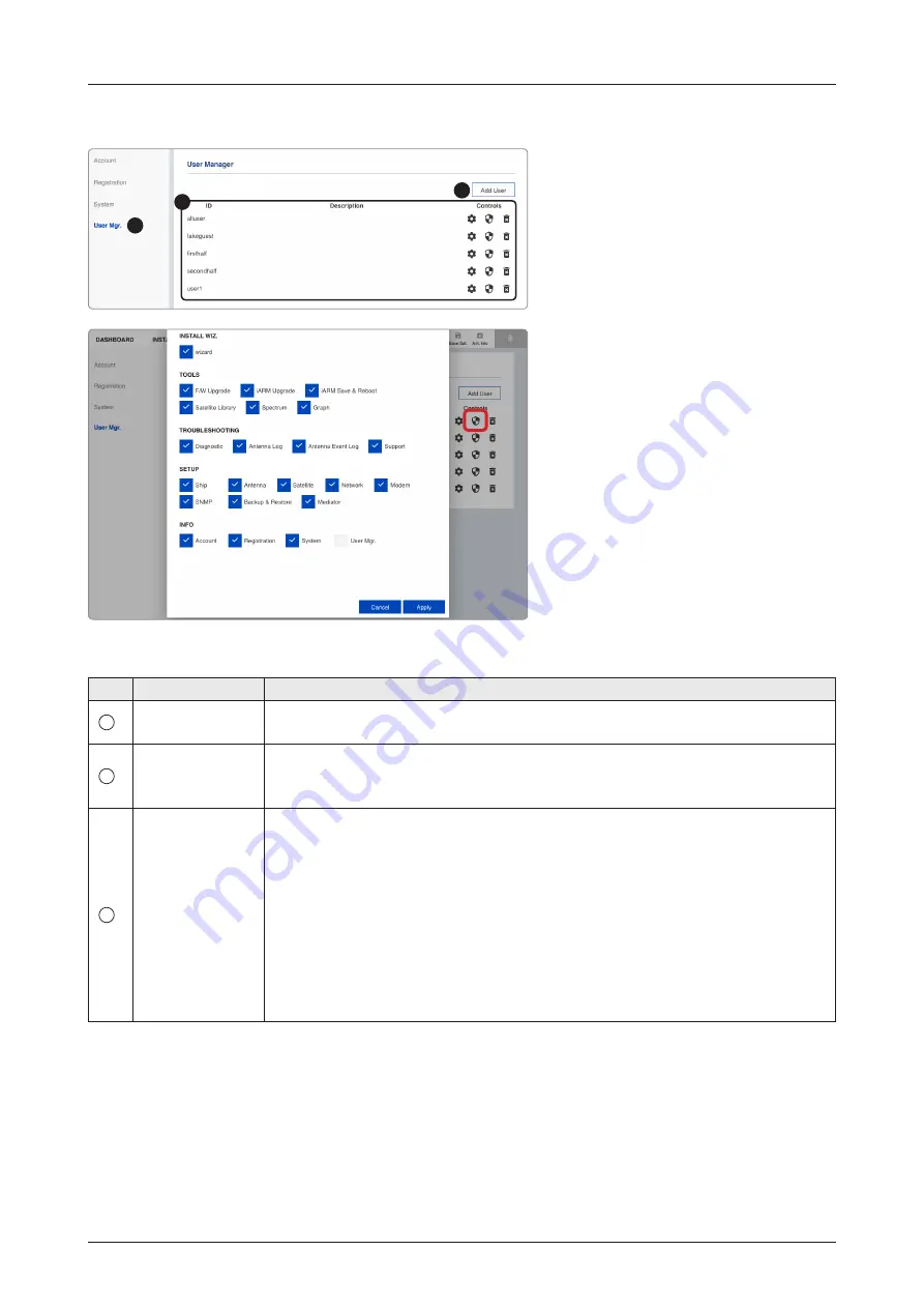
User Manager

No.

Item

Description 


1

User Manager

The captain with admin permissions can control and manage user permissions 
separately.


2

Add User

To add a new user, click the "Add User" button. The registration window will 
appear in the pop-up window. Enter the new user ID and password then click the 
"Add User" button.


3

User Management 
List

Displays the user management state and can control and manage through the 
control buttons.


• ID: displays the registered user ID.


• Description: displays the user's description.


• Controls: each user can be controlled and managed by individual settings.


- User Setting: reset the user ID by clicking the "Update User" button, and 

changes the password by clicking the "Reset Password" button.


- Edit Menu Permission: choose user permissions by clicking the checkbox. 

After selecting the options, click the "Apply" button. The user can only 
access the selected menus.


- Delete User: deletes the user.

1

2

3

Editable User Permissions Menu

Summary of Contents for GX100NX

Page 1: ...105cm Maritime VSAT Antenna System GX100NX Installation Operation User Guide...

Page 2: ......

Page 3: ...urnishing of this document does not give you any license to these patents trademarks copyrights or other intellectual property All other logos trademarks and registered trademarks are the property of...

Page 4: ...16 Antenna Specification 17 Antenna Dimensions 17 Heading Alignment 18 Antenna Mounting Hole Pattern 19 Mast Designing Installation Example 20 Option2 When Placing Cable Outside Mast 21 Preparing Ins...

Page 5: ...n 40 Name of BDT Rear Panel 40 Connecting to Antenna 40 Connecting to the Switch Router 41 Connecting Ship s Gyrocompass 41 How to Connect NMEA 0183 Gyrocompass Cable 42 Connecting to Additional Secon...

Page 6: ...in Page 81 Page Login 81 Top Menus 82 Account Menu 83 Account 83 Registration 84 System 85 User Manager 86 Dashboard 87 How to Add Remove Panels Dashboard Setting 87 How to Arrange Dashboard Layout 88...

Page 7: ...108 Backup Restore Setting 110 Mediator Setting Optional For Dual Antenna System 111 Specification Technical Specification 113 Environmental Specification 114 Warranty Warranty Policy 115 Appendix A...

Page 8: ...potentially hazardous situation which if not avoided could result in death or serious injury CAUTION CAUTION CAUTION indicates a potentially hazardous situation which if not avoided could result in mi...

Page 9: ...bpart B Product Information Product Name Intellian GX100NX Test Result Standard Test Rule Section Test Report Number Result FCC Part 15 Subpart B AC Power line conducted emission ANSI C63 4 2014 DREFC...

Page 10: ...g Annex II of Directive 2014 53 EU the following harmonized standards and normative documents are those to which the product s conformance is declared and by specific reference to the essential requir...

Page 11: ...to ensure reliable broadband communications The GX100NX is even more operator friendly by the integrated RF and power cables in one coaxial cable The single coaxial cable carries Tx Rx DC power data a...

Page 12: ...uick and Easy Deployment The GX100NX can be accessed through the external connector at the bottom of radome so that there is no need to open the radome for installation or pre test In addition the bui...

Page 13: ...and Antenna Unit Below Deck Termial BDT Below Deck Terminal BDT is the unit combined with various interfaces including ACU Modem Core Module and Ethernet Switch Below Deck Terminal BDT controls Antenn...

Page 14: ...cted to non Core Module installed Antenna Control Unit ACU instead of BDT The following functions are supported by ACU High power supply for the high power BUC Spectrum analyzer function included OLED...

Page 15: ...Kit to Install Antenna to Antenna Mast 1 Spare Set Included Flat Washer 5 M12 Spring Washer 5 M12 Hex Head Wrench Bolt 5 M6x40L Spare Bolt Kit for Radome Assembly Spring Washer Flat Washer 5 M6 Sems...

Page 16: ...o PC AC Power Cord CEEE7 7 1 1 5m ACU Power 220V RG 6 RF Cable 2 1m ACU to Modem Modem Interface Cable For iDirect Modem 1 1 5m ACU to Modem iDirect Modem Ethernet Cable RJ45 LAN 2 1m ACU to PC Intell...

Page 17: ...rall space occupied by the antenna must be sufficient for the height and diameter of the fully constructed radome The height and the diameter of the bottom surface of the antenna are as shown in the f...

Page 18: ...e assembly should be positioned with the BOW marker aligned as close as possible to the center line of the ship Figure Antenna Heading Alignment Front View BOW Direction Radome Hatch Radome Hatch Cabl...

Page 19: ...allation Antenna Mounting Hole Pattern The mounting holes must be in the exact same place as shown in the diagram below Figure Antenna Mounting Hole Pattern 247 5mm 9 74 445mm 17 5 445mm 17 5 247 5mm...

Page 20: ...mm 31 49 200 mm 7 87 Min 10 mm 0 39 Max 20 mm 0 78 22 mm 0 86 4 13 mm 0 51 247 5 mm 9 74 247 5 mm 9 74 254 mm 10 BOW Mast Designing Installation Example The installation mast must be robust enough to...

Page 21: ...tion Option2 When Placing Cable Outside Mast Figure Recommended Size of Mast Option2 1000 mm 39 37 840 mm 33 07 200 mm 7 87 Min 10 mm 0 39 Max 20 mm 0 78 22 mm 0 86 4 13 mm 0 51 247 5 mm 9 74 247 5 mm...

Page 22: ...g obstacles in way of the beam path will cause decreased satellite signal strength The antenna unit should have direct line of sight with the desired satellite without any obstacles in the beam path C...

Page 23: ...Hazard Precautions The antenna is designed to be used with radiation transmitting equipment manufactured by others Exposure to RF radiation including exposure associated with an improper use of the tr...

Page 24: ...ble types for standard system installations For cables that run longer than 120 meters except LMR600 coaxial cable type please consult Intellian Technologies The Maximum DC Resistance of RF Cable is 0...

Page 25: ...connector inside the cable entry adjust the cable length and then fix the cable on the cable bracket by using cable ties WARNING WARNING Ensure that cable has been run through watertight fittings to...

Page 26: ...the side panels with a paper sticker Unpack Guide Detach this side panel by removing the fixing screw 1 EA and clips 6 EA CAUTION CAUTION Be careful with the direction of the panel that you must open...

Page 27: ...the BDT to the RF Connector inside cable entry of radome Antenna 3 3 Execute diagnostic tests Full Diagnosis Test via BDT and check the real time diagnosis result 4 Remove the clips 6 EA on the top pa...

Page 28: ...tenna using the lifting straps make sure to remove the securing radome brackets to separate antenna from the pallet Be careful when lifting the heavy object Incorrect handling of the heavy object may...

Page 29: ...h the BOW marker aligned as close as possible to the ship s heading WARNING WARNING The antenna may be subject to swaying motions in windy conditions Be careful when handling the antenna Fully Tighten...

Page 30: ...waterproof foam to expose the adhesive 2 Attach the waterproof foam firmly onto the surface of the cable access hole 3 Pull the RF cable from the mast Attaching Position of Waterproof Foam Cable Acce...

Page 31: ...ome and fasten them to the nuts assembled inside the radome After mounting the antenna on the mast remove the lifting strap Use 19 mm Spanner Torque Wrench M12x80L Hex Bolt M12 Flat Washer M12 Spring...

Page 32: ...the cable ties in place 1 Remove the M4x15L Wrench Bolt by using the wrench set then open the cable entry cover 2 Terminate N M connector on the end of the RF Cable Intellian recommends using a genui...

Page 33: ...m the BDT box Open the radome hatch by turning the fixed bolts counterclockwise by using the radome door key 2 The power box switch was turned on and shipped from the factory Check the power box insid...

Page 34: ...mm 18 34 431 mm 16 96 485 mm 19 09 BDT Dimensions Confirm the dimension of the BDT before installing it Installing Below Deck Unit BDU Selection of BDU Installation Site The BDU should be installed b...

Page 35: ...d 19 Rack Mounting Brackets Using the Flat Head Screw supplied attach the mounting brackets to the sides of the BDT Place the BDT in the location where it is going to be installed Connect the cables t...

Page 36: ...k Unit BDU Figure ACU Dimensions 350 mm 13 77 376 mm 14 80 32 mm 1 25 44 3 mm 1 74 466 mm 18 34 431 mm 16 96 485 mm 19 09 ACU Dimensions Optional For Dual Antenna System Confirm the dimension of the A...

Page 37: ...g the two supplied 19 Rack Mounting Brackets Using the Flat Head Screw supplied attach the mounting brackets to the sides of the ACU Place the ACU in the location where it is going to be installed Con...

Page 38: ...router and ship s gyrocompass may be required Single Antenna System Configuration Basic Antenna System The Basic system consists of one VSAT antenna and one BDT As shown in the configuration below co...

Page 39: ...t the cables correctly Figure Dual Antenna System Configuration NOTE NOTE The description of this Dual Antenna System is written on the Appendix A chapter Refer to the Using Dual Antenna System Option...

Page 40: ...na Connector LAN 2 Port LAN 1 Port LAN 4 Port LAN 3 Port Secondary Rx TX Connector Power Cord Connecting to Antenna Connect the RF Cable not supplied by Intellian from the ANTENNA connector on the rea...

Page 41: ...yrocompass to the antenna system through the gyrocompass interface on the rear of the BDT Intellian s BDT supports NMEA 0183 and NMEA 2000 gyrocompass inputs If the ship s gyrocompass output uses a di...

Page 42: ...sitive and negative cables Connecting to Additional Secondary ACU Optional For Dual Antenna System To use the Dual Antenna System the antenna system needs to be installed with the BDT and an addtional...

Page 43: ...ial BDT Pin Signal 1 NC 2 DBG RX iARM 3 DBG TX iARM 4 NC 5 GND 6 NC 7 NC 8 NC 9 NC RS232 Connector iARM Interface Cable Connector ins Male Connector hreads 5 3 4 1 2 Sockets Connector Threads 5 4 3 2...

Page 44: ...44 Installing Below Deck Unit BDU LAN Ports Pin Signal 1 Tx 2 Tx 3 Rx 4 NC 5 NC 6 Rx 7 NC 8 NC LAN 1 4 Ports Below Deck Termial BDT LAN Ports Cable Connector...

Page 45: ...on is established automatically 3 Use the following IP address to access Intellian AptusNX page IP Address 192 168 2 1 Default Management LAN Port BDT Front Panel Figure Front Panel Management LAN Por...

Page 46: ...ian AptusNX page IP Address 192 168 2 1 Default 4 Log into the AptusNX by typing in User Name and Password information If this system has not been changed from the factory default User Name intellian...

Page 47: ...without the need for additional PC IP configuration 1 Connect an Ethernet cable from the Management LAN port on the front of the BDT to the LAN port of PC 2 The network connection is established autom...

Page 48: ...urpose and action buttons to set the values After accessing the AptusNX main page go to the INSTALL WIZ on the main menu then follow these steps Welcome Page Description Displays the welcome message C...

Page 49: ...S signal is abnormal or the received value is incorrect Error Black the system has not received a GPS signal You can enter the GPS value manually to set the GPS position If you have no problems click...

Page 50: ...tion block starts Range 0 90 If you have no problems click the Next button Step 4 Set Bow Offset For setting bow offset a trackable satellite must be selected When Antenna tracks the selected satellit...

Page 51: ...e target satellite that you want to track There are two methods for selecting a target satellite NOTE NOTE The following images in this step show when the system is using the Open AMIP modem Option 1...

Page 52: ...iption Displays the configuration report You can save the results to the BDT by clicking the Save Report button and download the report file json by clicking the Export button Click the View Last Repo...

Page 53: ...ulty TRACKING Indicator Select Key Power Button ERROR Indicator POWER Indicator OLED Display Move Key Left USB Port Only for Service Engineer Right USB Port For Log Data Download Backup Restore Antenn...

Page 54: ...ays that the antenna system is in progress firmware upgrades A This function is available when using the Dual Antenna System Displays the antenna s active state The active antenna either primary or se...

Page 55: ...dem is connected to a target satellite and acquired a network Abnormal The modem network is in abnormal conditions Off The modem is not connected to a target satellite and not acquired a network TX On...

Page 56: ...ormation Initialize Elevation Angle Initialize Azimuth Angle Antenna s Status in Search 1 Global Search Search 3 Local Search Tracking Beam Switching Blocking SNR HDG 120 4 GPS A P SEARCH 1 128 0 E CM...

Page 57: ...ontrol Mode Status in Reboot Mode Setup Mode Test Mode One Touch Commissioning If the antenna is not communicating with BDT the COMMUNICATION ERROR message will appear When the antenna is controlled b...

Page 58: ...test and shows the real time diagnosis result Diagnosis DIAGNOSIS DIAG ALL DIAG CODE 101 1 O O 7 O O 10 O O 13 14 O O Press Move Key Press Select Key Refer to the diagnosis codes for the test results...

Page 59: ...e 110 The LNB NBD is tested 111 Not Available 112 Not Available 113 The antenna power is tested 114 The ACU power is tested 115 Not Available 116 The home sensor is tested 2 Diagnosis Result An exampl...

Page 60: ...erial Number Displays the Antenna serial number The serial number is displayed depending on the product 2 PCU Version STAB Version Displays the PCU version Stabilizer version 3 ACU Serial Number Displ...

Page 61: ...in Display Diagnosis Display Antenna Information Display The XX is the model name and the xxxx is antenna ACU serial number Interface Information Display Refer to the Interface Information No Item Des...

Page 62: ...about each function refer to the next page INTERFACE MODEM IDIRECT AMIP HEADING NONE NETWORK 1 3 USB FUNCTION USB SEL PRODUCT XXXXXXX ANT xxxxxxxxx VER 1 00 1 00 ACU xxxxxxxxxxxxx VER 1 00 1 00 Press...

Page 63: ...MONTHS LOG LOG DOWNLOAD BACK 1 WEEK LOG 1 MONTH LOG 3 MONTHS LOG Press Select Key Press Move Key Press Move Key Press Select Key Press Select Key Press Select Key USB Function Menu Display Log Downloa...

Page 64: ...t the BACK option then press the Select key INVALID BACK FILE FORMAT FILE BACK NOT FOUND If the firmware file does not match the file format the INVALID FILE FORMAT message will appear If there is no...

Page 65: ...BACK LOG DOWNLOAD FIRMWARE UPLOAD BACKUP TO USB RESTORE FROM USB Press Select Key x3 times Press Move Key BACKUP TO USB Backs up the antenna setting files to the USB NOTE NOTE When you want to return...

Page 66: ...OAD BACKUP TO USB RESTORE FROM USB USB FUNCTION BACK LOG DOWNLOAD FIRMWARE UPLOAD BACKUP TO USB RESTORE FROM USB Press Select Key x4 times Press Move Key RESTORE FROM USB Restores the antenna setting...

Page 67: ...n The antenna is in tracking mode TRACKING Indicator Select Key Power Button ERROR Indicator POWER Indicator OLED Display Move Key Management Port Introduction Antenna Control Unit ACU To use the Dual...

Page 68: ...s the antenna system status Display Description M This function is available when using the Dual Antenna System Displays that the antenna system is in manual mode U Displays that the antenna system is...

Page 69: ...on Initialize Elevation Angle Initialize Azimuth Angle Antenna s Status in Search 1 Global Search Search 3 Local Search Tracking Beam Switching Blocking SNR F 20 119 18 250 RX L TX R SEARCH 1 128 0 E...

Page 70: ...T MODE COMMUNICATION ERROR Control Mode Status in Reboot Mode Setup Mode Test Mode If the antenna is not communicating with ACU the COMMUNICATION ERROR message will appear When the antenna is controll...

Page 71: ...Diagnosis test and shows the real time diagnosis result Diagnosis DIAGNOSIS DIAG ALL DIAG CODE 101 1 O O 7 O O 10 O 13 14 O O Press Move Key Press Select Key Refer to the diagnosis codes for the test...

Page 72: ...e 110 The LNB NBD is tested 111 The LNB pol motor is tested 112 Not Available 113 The antenna power is tested 114 The ACU power is tested 115 Not Available 116 The home sensor is tested 2 Diagnosis Re...

Page 73: ...tion 1 Antenna Serial Number Displays the Antenna serial number The serial number is displayed depending on the product 2 PCU Version STAB Version Displays the PCU version Stabilizer version 3 ACU Ser...

Page 74: ...Key Main Display Diagnosis Display Antenna Information Display The XX is the model name and the xxxx is antenna ACU serial number Interface Information Display Refer to the Interface Information No It...

Page 75: ...mation about each function refer to the next page INTERFACE MODEM IDIRECT AMIP HEADING NONE NETWORK 1 3 USB FUNCTION USB SEL PRODUCT XXXXXXX ANT V0918070001 VER 1 00 1 00 ACU V0918070001 VER 1 00 1 00...

Page 76: ...OG 3 MONTHS LOG LOG DOWNLOAD BACK 1 WEEK LOG 1 MONTH LOG 3 MONTHS LOG Press Select Key Press Move Key Press Move Key Press Select Key Press Select Key Press Select Key USB Function Menu Display Log Do...

Page 77: ...ollow the folder structure guide to configure the folders properly It supports up to FAT32 The antenna system is upgraded with the FWP file in the designated folder of a USB memory stick GX100NX GX100...

Page 78: ...LOG DOWNLOAD FIRMWARE UPLOAD BACKUP TO USB RESTORE FROM USB Press Select Key Press Select Key x3 times Press Move Key BACKUP TO USB Backs up the antenna setting files to the USB NOTE NOTE When you wa...

Page 79: ...UPLOAD BACKUP TO USB RESTORE FROM USB USB FUNCTION BACK LOG DOWNLOAD FIRMWARE UPLOAD BACKUP TO USB RESTORE FROM USB Press Select Key x4 times Press Move Key RESTORE FROM USB Restores the antenna sett...

Page 80: ...nd system Diagnosis How to access AptusNX for BDT 1 Connect an Ethernet cable from the Management LAN port on the front of the BDT to the LAN port of PC This method is most recommended 2 Enter the BDT...

Page 81: ...is system has not been changed from the factory default User Type User ID Password Access Authority Admin intellian 12345678 Supports all menus for monitoring and setting captain 12345678 Supports all...

Page 82: ...able to transmit data 6 Lock Displays whether or not the satellite is locked 7 Main Menu SelectstheMainMenu DASHBOARD INSTALLWIZ TOOLS TROUBLESHOOTING SETUP Each main menu offers side menus on the lef...

Page 83: ...t User ID displays your user ID User ID enter the current user ID Current Password enter the current password New Password enter the new password Confirm New Password re enter the new password to veri...

Page 84: ...Enters the vessel information There are two options whether using the IMO number or not When you have the IMO number select the Yes button and enter the IMO Number When you do not have the IMO number...

Page 85: ...the antenna S W version and network IP address 2 Antenna Information Displays antenna information 3 S W Version Information Displays S W version information 4 Network Information Displays network inf...

Page 86: ...ment state and can control and manage through the control buttons ID displays the registered user ID Description displays the user s description Controls each user can be controlled and managed by ind...

Page 87: ...range your panels in various ways to make them more readable and user friendly How to Add Remove Panels Dashboard Setting Adding Panels 1 On the right side of the page you will see the gear icon to ed...

Page 88: ...from the dashboard 3 Click the Apply button to apply the settings to the system 1 3 2 How to Arrange Dashboard Layout You can customize the dashboard by rearranging panels as you wish 1 Click and hold...

Page 89: ...n and manage the each panel s settings 1 Click the Shortcut button indicated by the red mark to open the setting page 2 The setting page will appear on the individualized web page You can check the de...

Page 90: ...o your antenna and BDT Please check firmware version before uploading firmware Upgrade Method selects an upgrade method between Manual Upgrade or Auto Upgrade NOTE when using the Manual Upgrade method...

Page 91: ...ecting the box Ignore warnings during installation and force the installation to continue before performing the upgrade the warning messages do not appear during the upgrade 2 The antenna firmware sta...

Page 92: ...current bootstrap and bootloader version Bootstrap displays the Bootstrap Version Main Factory Default Bootloader displays the Bootloader Version Main Factory Default Active Bootloader 4 Kernel File...

Page 93: ...upgrade WARNING WARNING Do not turn off the device power if the firmware upgrade page is displayed Failure to comply may lead to damage and or malfunction of the system 3 Once the upgrade is completed...

Page 94: ...te List then Click the Load Satellite button to load the satellite information 4 Common Information Displays selected satellite information Satellite Name displays the satellite name Longitude display...

Page 95: ...the graphs of only the checked item s in the Multi Chart Single Chart or AZ EL formats Multi Chart displays multiple graph Items in one graph View Single Chart displays the checked graph Item in each...

Page 96: ...checkbox full diagnosis test or single diagnosis test before modifying the settings Select All select to run a full diagnosis test Clear Select select to run a single diagnosis test View Last Result...

Page 97: ...m You can save the results to the BDT by clicking the Save Result button and print this page by clicking the Print button To remove the result click the Clear Diagnosis button 4 When you want to check...

Page 98: ...ny log data within three months can be downloaded Select the duration on the calendar view that you want to show Then click the Start Download button NOTE when selecting the box Include Backup Report...

Page 99: ...show Tracking Method sets the sorting type Descending Ascending Click the Query Event Log button to apply the settings to the system 3 Event Log Displays event log information Antenna Event Log 1 2 3...

Page 100: ...tellite Check the GPS status connected to the antenna system The indicator left of the help button shows the GPS status Please confirm the GPS indicator is Blue blinking Blue blinking the system recei...

Page 101: ...elect a satellite which is trackable in satellite library information When the antenna tracks the selected satellite bow offset will be set up automatically Current Bow Offset enter the Bow Offset Ran...

Page 102: ...Sets current antenna position and search parameters These parameters should only be changed by an authorized service technician Improper setting of these parameters will render your system inoperable...

Page 103: ...levation Sets the conical range while the antenna is in tracking mode Click the Apply button to apply the settings to the system 6 Conical Range Check Enter Setup Mode to modify settings Monitors the...

Page 104: ...ship s motion roll pitch and yaw for stabilizing the pedestal The DC voltage output from each of the rate sensors may vary by an amount which is directly proportional to the direction and rate of mot...

Page 105: ...zation sets the current RX polarization TX Polarization sets the current TX polarization Click the Apply button to apply the settings to the system 3 NBD Information Sets NBD mode s tracking informati...

Page 106: ...the network IP address Factory default 192 168 2 1 Subnet Mask sets the subnet mask Factory default 255 255 255 0 Lease Start Address sets the lease IP address start range Lease End Address sets the...

Page 107: ...s the HTTPS port number SSH Service sets the SSH service status Disable Enable Click the Apply button to apply the settings to the system 5 Sys Log Configuration Sets the system log configuration Ante...

Page 108: ...108 Using AptusNX Modem Info 1 2 3 4 6 5...

Page 109: ...f The modem Tx services are not active RX1 Steady Green The modem Rx 1 services are active Steady Yellow The modem Rx 1 is in abnormal conditions Off The modem Rx 1 services are not active RX2 Steady...

Page 110: ...etup Mode to modify settings Restores the antenna setting by using the setting files saved from BDT or PC Click the Restore button to apply the settings to the system 3 iARM Backup Restore iARM Backup...

Page 111: ...e Reboot on page 93 3 Antenna Active This function is available in the Primary Antenna s AptusNX when both Primary Role s BDT and Secondary Role s ACU are connected to the system Sets the method for s...

Page 112: ...ifference between the active antenna and inactive antenna is more than the set value which is set in the Signal Level menu and the difference is maintained for a set time the active antenna is automat...

Page 113: ...29 GHz 30 GHz Ka band Gain 47 7 dBi 29 5 GHz with radome Above Deck IFL Termination 1 x 50 Ohm N type female connector TX RX 10 MHz 50 MHz 400 MHz 433 MHz L band 950 MHz 2150 MHz DC power to BUC pede...

Page 114: ...urvival Bump IEC 60068 2 29 Method Eb 25g 6ms Salt mist Saline solution 5 1 NaCl Storage period 7 Days IEC 60945 Waterproofing IPX6 IEC 60529 Solar IEC 60945 Annex B Operational 32 C air temperature w...

Page 115: ...s the date of purchase for after sales service under the warranty period In case of failure to present the purchase receipt the warranty period will begin 30 days after the manufacturing production da...

Page 116: ...tion Optional on page 39 for more details Access the AptusNX IP Address 192 168 2 1 to manage and control the Dual Antenna System You can check the status of Dual Antenna System via AptusNX The inform...

Page 117: ...he front of the BDT to the LAN port of PC Management LAN Port PC Not supplied 2 Use the following IP address to access iDirect webpage Default IP 192 168 1 1 3 Login to the iDirect modem page using th...

Reviews: