2.2
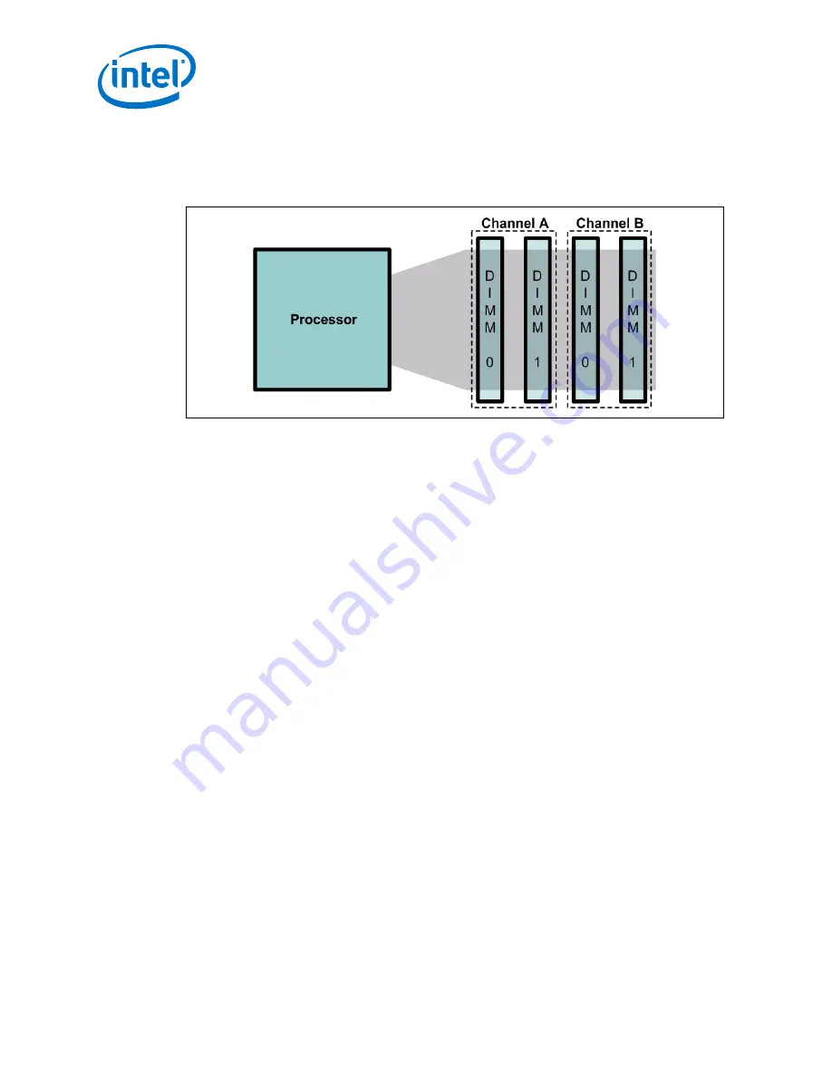
Memory Module Plug-in
Figure 6.
Memory Sockets
Note:
See
on page 10 for memory specific information.
1. Beginning with Channel A - DIMM1, line up the DIMM with the slot and make sure
that the end clips are moved outward to the open position.
2. Gently push the DIMM into the socket until you hear or feel the end clips lock into
the side of the DIMM.
3. Continue adding memory in accordance with
2.3
Peripheral Setup
2.3.1
Connect SATA Cables
There are two Serial ATA (SATA) connectors on the CRB. Connect the cables to the
appropriate drive sequentially starting from SATA Port 0 through Port 1.
Note:
Intel recommends using SATA Port 0 as the boot drive (Port 4 in the Intel
®
Communications Chipset 89xx Series documentation).
2.3.2
Expansion Connectors
If necessary, connect PCI Express* add-in cards, possibly including the video card, in
the appropriate Slot 1 through Slot 6 PCI Express slots.
•
Slot 1 is a x4 link with a x8 connector. Some systems may not support Slot 1 or
may have issues training with Slot 1. If you encounter issues with Slot 1, try a
different slot.
•
Slot 2 is a x8 link with a x16 connector (option for x16 link muxed with the Intel
®
Communications Chipset 89xx Series End-Point). Some systems may have issues
training with Slot 2. If you encounter issues with Slot 2, try a different slot.
•
Slots 3, 4, 5, and 6 are x1 link widths with x8 connectors.
Crystal Forest—CRB Setup
Intel
®
Xeon
®
Processor E3-1125C with Intel
®
Communications Chipset 8910 Development Kit
User Guide
October 2012
22
Order No.: 328009-001US


