


Intel
®
Server Chassis P4304XXMFEN2/P4304XXMUXX Product Family System Integration and Service Guide
29
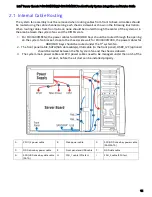
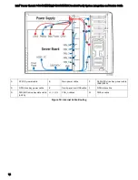
2.6
Memory Installation and Removal
2.6.1
Memory Slot Population Requirements
Note:
Some system configurations may come with pre-installed DIMM blanks. DIMM blanks should only
be removed when installing a DIMM in the same DIMM slot. Memory population rules apply when
installing DIMMs.
•
DIMM Population Rules on CPU-1
– Install DIMMs in order; Channels A, B, C, and D. Start with the
1
st
DIMM (Blue Slot) on each channel, then slot 2.
•
DIMM Population Rules on CPU-2
– Install DIMMs in order; Channels E, F, G, and H. Start with the
1
st
DIMM (Blue Slot) on each channel, then slot 2.
•
The following system configurations require that specific memory slots be populated at all times
using either a DIMM or supplied DIMM blank.
2.6.2
Memory Installation
Figure 21. Installing Memory
1.
Locate the DIMM sockets. Make sure the clips at either end of the DIMM socket(s) are pushed
outward to the open position (see letter “A”).
2.
Holding the DIMM by the edges, remove it from its anti-static package. Position the DIMM above the
socket. Align the notch on the bottom edge of the DIMM with the key in the DIMM socket (see letter
“B”).
3.
Insert the bottom edge of the DIMM into the socket (see letter “C”). When the DIMM is inserted,
push down on the top edge of the DIMM until the retaining clips snap into place (see letter “D”).
Make sure the clips are firmly in place (see letter “E”).


