background image

Intel

®

 Server Chassis P4304XXMFEN2/P4304XXMUXX Product Family System Integration and Service Guide 


28  


2.5.3


Processor Heatsink Installation 


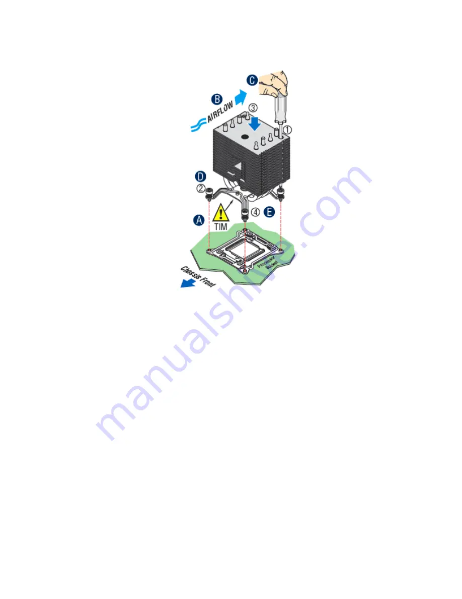
Figure 20. Processor Heatsink Installation 

1.


If present, remove the protective film covering the Thermal Interface Material on the bottom side of 

the heatsink (see letter “A”). 

2.


Align heatsink fins to the front and back of the chassis for correct airflow. Airflow goes from front to 

back of the chassis (see letter “B”). 
Each heatsink has four captive fasteners and should be tightened in a diagonal manner using the 

following procedure: 

3.


Using a #2 Phillips* screwdriver, start with screw 1 and engage screw threads by giving it two 

rotations and stop (see letter “C”). (Do not fully tighten.) 

4.


Proceed to screw 2 and engage screw threads by giving it two rotations and stop (see letter “D”). 

Similarly, engage screws 3 and 4. 

5.


Repeat steps C and D by giving each screw two rotations each time until each screw is lightly 

tightened up to a maximum of 8 inch-lbs torque (see letter “E”). 

2.5.4


Removing the Processor 

1.


Remove the processor heatsink (see section 2.5.1). 

2.


Unlatch the CPU Load Plate (see section 2.5.2). 

3.


Lift  the Load Plate (see section 2.5.2). 

4.


Remove the processor by carefully lifting it out of the socket, taking care NOT to drop the processor 

and not touching any pins inside the socket. 

5.


Install the socket cover if a replacement processor is not going to be installed. 

Summary of Contents for P4304XXMFEN2

Page 1: ...l Server Chassis P4304XXMFEN2 P4304XXMUXX Product Family System Integration and Service Guide A Guide for Technically Qualified Assemblers of Intel identified Subassemblies Products Revision 1 3 May 2...

Page 2: ...MANUFACTURE OR WARNING OF THE INTEL PRODUCT OR ANY OF ITS PARTS Designers must not rely on the absence or characteristics of any features or instructions marked reserved or undefined Intel reserves t...

Page 3: ...auf der http www intel com support motherboards server sb cs 010770 htm Consignes de s curit Lisez attention toutes les consignes de s curit et les mises en garde indiqu es dans ce document avant de s...

Page 4: ...ersonal injury or equipment damage can result Electrostatic discharge ESD and ESD protection ESD can damage disk drives boards and other parts We recommend that you perform all procedures in this chap...

Page 5: ...are chassis and installing all the system boards and major server components including power supply and system fans This chapter can be skipped if the server board and other major components are pre i...

Page 6: ...echnical Product Specification For a list of available systems within the product family and supported Intel spares and accessories Intel Server Board S2600CW Product Family Spares and Accessories Lis...

Page 7: ...Essential System Component Installation and Service 14 2 1 Internal Cable Routing 15 2 2 Chassis Side Cover Removal Installation 17 2 2 1 Chassis Side Cover Removal 17 2 2 2 Chassis Side Cover Instal...

Page 8: ...n Removal 63 3 3 1 Installing the LSI IMR RAID 5 Key 63 3 3 2 Removing the LSI IMR RAID 5 Key 63 3 4 Intel RAID Smart Battery AXXRSBBU9 Installation Removal 64 3 4 1 Intel RAID Smart Battery Pre Insta...

Page 9: ...Server Chassis P4304XXMFEN2 P4304XXMUXX Product Family System Integration and Service Guide ix Appendix A Getting Help 82 Appendix B POST Code Diagnostic LED Decoder Table 83 Appendix C POST Code Erro...

Page 10: ...tallation Close the Load Plate 27 Figure 19 Processor Installation Latch the Locking Lever 27 Figure 20 Processor Heatsink Installation 28 Figure 21 Installing Memory 29 Figure 22 Removing Memory 30 F...

Page 11: ...Features Overview 73 Figure 44 Intel Server Chassis P4304XXMUXX Features Overview 74 Figure 45 No Front Drive Bay Configuration Chassis only Building Block 74 Figure 46 P4304XXMFEN2 P4304XXMUXX Front...

Page 12: ...1 Server Chassis References vi Table 2 BIOS Setup Keyboard Command Bar 71 Table 3 POST Progress Code LED Example 84 Table 4 MRC Progress Codes 84 Table 5 MRC Fatal Error Codes 85 Table 6 POST Progres...

Page 13: ...and ESD precautions found in the Warnings section at the beginning of this manual Tools and Supplies Needed Anti static wrist strap and conductive foam pad recommended Phillips cross head screwdriver...

Page 14: ...rds I Power Connector E RMM4 NIC Port Optional Figure 1 Intel Server Chassis P4304XXMFEN2 Fixed Power Supply A Power Connector filler only F RMM4 NIC Port Optional B Power Connector filler only G Seri...

Page 15: ...chassis inside 1 2 2 Installing the IO Shield Note The IO shield can be found in the retail board package or can be ordered separately From the chassis inner side align the IO shield to the chassis r...

Page 16: ...Intel Server Chassis P4304XXMFEN2 P4304XXMUXX Product Family System Integration and Service Guide 4...

Page 17: ...oard placement Remove the server board from its anti static bag Attach the bumpers to the back of the server board Carefully lower the server board into the chassis so that the rear I O connectors of...

Page 18: ...wer supply is already installed If the chassis model is P4304XXMUXX one or two separate power supplies need to be ordered separately and installed in the server chassis The server chassis P4304XXMUXX...

Page 19: ...Intel Server Chassis P4304XXMFEN2 P4304XXMUXX Product Family System Integration and Service Guide 7...

Page 20: ...Intel Server Chassis P4304XXMFEN2 P4304XXMUXX Product Family System Integration and Service Guide 8 Figure 5 Installing 1600W Power Supply...

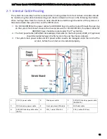
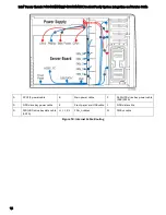
Page 21: ...r P4304XXMFEN2 the power cables for HDD ODD bays should be routed through the opening on the system fan bracket close to the chassis side wall for P4304XXMUXX the power cables for HDD ODD bays should...

Page 22: ...nd Service Guide 10 A CPU1 2 power cable B Main power cable C SSD HDD drive bay power cable SAS SATA D ODD drive bay power cable E Front panel and USB cable F ODD data cable G SSD HDD drive bay data c...

Page 23: ...tor to the server board close to the server edge silkscreen labeled MAIN_PWR Connect the 2x4 pin cable connector to the server board close to CPU1 silkscreen labeled CPU_1_PWR Connect the 2x4 pin cabl...

Page 24: ...m fans to the fan headers on the board silkscreen labled SYS_FAN_1 and SYS_FAN_2 2 For server chassis P4304XXMUXX connect the cables of the five system fans to the fan headers on the board silkscreen...

Page 25: ...necting the Cables to the Front Panel 1 Connect the front panel cable to the 2x12 SSI compliant front panel connector on the server board edge silkscreen labeled SSI_FRONT_PANEL 2 Connect the USB 3 0...

Page 26: ...r product observe the safety and ESD precautions found in the Warnings section at the beginning of this manual Tools and Supplies Needed Anti static wrist strap and conductive foam pad recommended Phi...

Page 27: ...should be routed through the opening on the system fan bracket close to the chassis side wall for P4304XXMUXX the power cables for HDD ODD bays should be routed under the 5th system fan 2 The front pa...

Page 28: ...and Service Guide 16 A CPU1 2 power cable B Main power cable C SSD HDD drive bay power cable SAS SATA D ODD drive bay power cable E Front panel and USB cable F ODD data cable G SSD HDD drive bay data...

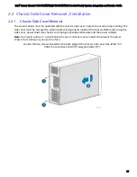
Page 29: ...ling The side cover must be removed to add or replace components inside of the chassis Before removing the side cover power down the chassis and unplug all peripheral devices and the power cable s Not...

Page 30: ...ice Guide 18 2 2 2 Chassis Side Cover Installation 1 Place the chassis side cover onto the chassis and slide forward until the front edge of the cover is pressed up against the back edge of the front...

Page 31: ...hassis 2 3 1 Air Duct Installation 1 Manage the system main power cable and CPU power cables under the notch of the air duct 2 Align the two tabs on the front edge of the air duct with the matching sl...

Page 32: ...outing cables inside the chassis from back to front or from front to back or when server board replacement is necessary 2 4 1 System Fan Assembly Removal To remove the hot swap system fan from P4304XX...

Page 33: ...ation and Service Guide 21 To remove the fixed system fan CPU fan or PCIe fan from P4304XXMFEN2 1 Unplug the fan cable from the server board see letter A 2 Open the two latches on both sides of the sy...

Page 34: ...nstall the hot swap system fan on P4304XXMUXX Align the two guide pins on the fan with the openings located on the fan bracket Carefully lower the fan so the guide pins slide lower into the openings C...

Page 35: ...Route the fixed fan cable through the fan holder Align the fixed fan with the fan holder and press the fixed fan until it clicks and fits into place Connect the fixed fan cable to the system fan conne...

Page 36: ...Using a 2 Phillips screwdriver loosen the four screws located on the heatsink corners in a diagonal manner using the following procedure Using a 2 Phillips screwdriver start with screw 1 and loosen i...

Page 37: ...s before touching the processor or server board Keep part of your body in contact with the metal chassis to dissipate the static charge while handling the processor 2 Avoid moving around unnecessarily...

Page 38: ...hen installing the CPU Figure 16 Processor Installation Install the Processor Remove the processor from its packaging Carefully remove the protective cover from the bottom side of the CPU taking care...

Page 39: ...rocessor 6 Lock down the Load Plate Figure 19 Processor Installation Latch the Locking Lever Push down on the locking lever on the CLOSE 1st side see letter A Slide the tip of the lever under the notc...

Page 40: ...r start with screw 1 and engage screw threads by giving it two rotations and stop see letter C Do not fully tighten 4 Proceed to screw 2 and engage screw threads by giving it two rotations and stop se...

Page 41: ...1st DIMM Blue Slot on each channel then slot 2 The following system configurations require that specific memory slots be populated at all times using either a DIMM or supplied DIMM blank 2 6 2 Memory...

Page 42: ...ice Guide 30 2 6 3 Removing Memory Figure 22 Removing Memory 1 Locate the DIMM sockets Unlatch the retaining clips located on each end of the socket The DIMM lifts from the socket see letter A 2 Holdi...

Page 43: ...nk installed The server chassis P4304XXMFEN2 and P4304XXMUXX support various storage options Basic configuration Four 3 5 fixed drive trays are the default chassis configuration Upgrade Option One opt...

Page 44: ...with chassis 4x3 5 hot swap backplane cage MiniSAS HD to MiniSAS HD AXXCBL380HDHD Both server board and backplane side are MiniSAS HD type 8 drives Two 4x3 5 hot swap backplanes cages MiniSAS HD to Mi...

Page 45: ...l Before accessing the storage device the front bezel needs to be removed 1 Remove the chassis side cover following the instruction in session Chassis Side Cover Removal 2 Push the two tabs on the fro...

Page 46: ...ssembly against the right side of the chassis Engage the plastic bezel hooks see letter A into the raised metal slots at the chassis edge Rotate the bezel assembly toward the chassis Latch the two pla...

Page 47: ...erver Chassis P4304XXMFEN2 P4304XXMUXX Product Family System Integration and Service Guide 35 Remove the fillers for 5 25 drive slots if required Remove the cosmetic top board Install the front panel...

Page 48: ...sis P4304XXMFEN2 P4304XXMUXX Product Family System Integration and Service Guide 36 Install the 5 25 drive if required Install the rack bezel frame NOTE The rack bezel frame is different from the pede...

Page 49: ...Intel Server Chassis P4304XXMFEN2 P4304XXMUXX Product Family System Integration and Service Guide 37 Install the rack mount handles Install the rack bezel optional...

Page 50: ...Intel Server Chassis P4304XXMFEN2 P4304XXMUXX Product Family System Integration and Service Guide 38 Lock the front bezel key...

Page 51: ...04XXMFEN2 and P4304XXMUXX support four 3 5 fixed drive trays with their default configuration To install a fixed drive Remove the chassis side cover following instructions in section Chassis Side Cove...

Page 52: ...ct Family System Integration and Service Guide 40 Release the fixed drive tray by pressing the latches on both sides of the tray and pull the drive tray until it is fully removed from the chassis Secu...

Page 53: ...er Chassis P4304XXMFEN2 P4304XXMUXX Product Family System Integration and Service Guide 41 Slide the fixed drive tray back into the chassis until it clicks into place Install the EMI cover to the chas...

Page 54: ...der to the onboard connector labeled as sSATA_0 3 or SATA_0 3 On fixed drive side connect the SATA power header and the 7 pin SATA cable header A cable example is shown as below The header on the left...

Page 55: ...ver chassis support fixed drive storage by default the optional 4x3 5 or 8x2 5 hot swap drive bays and cables can be ordered separately and installed in the server chassis as upgrade options Remove th...

Page 56: ...tegration and Service Guide 44 Install the EMI cover by aligning the latch on the EMI cover to the chassis front and slide down see letter A and B Slide the 4x3 5 or 8x2 5 hot swap drive bay to the up...

Page 57: ...labeled as sSATA_0 3 or SATA_0 3 If using an 8x2 5 hot swap drive tray connect the miniSAS HD cable header to both sSATA_0 3 and SATA_0 3 Connect the other end of the miniSAS HD cable header to the b...

Page 58: ...NVMe add in card 8x2 5 SAS PCIe SSD NVMe combo drive bay NVMe cables MiniSAS to miniSAS cables optional I2C cable 1 Follow the same steps 1 4 in the previous section Upgrading the Fixed Drive Storage...

Page 59: ...rd HSBP_I2C header to the backplane I2C_IN SMBus in header 6 If regular SATA SAS drives will be used in drive slot 0 3 connect the miniSAS HD to miniSAS HD cable to the backplane connector G If SATA S...

Page 60: ...ive 3 Mini SAS HD cable connector D PCIe SSD Drive 2 Mini SAS HD cable connector E PCIe SSD Drive 1 Mini SAS HD cable connector F PCIe SSD Drive 0 Mini SAS HD cable connector G SATA SAS Ports 0 3 Mini...

Page 61: ...the server board SATA SAS connectors and the port B and G on the backplane The 8x2 5 SAS NVMe combo backplane is capable of supporting 12 Gb SAS or 6 Gb SAS SATA drives The SAS SATA drives are hot swa...

Page 62: ...ge Remove the chassis side cover following instructions in section Chassis Side Cover Removal Remove the front bezel following instructions in section Removing the Front Bezel Remove the fixed drive t...

Page 63: ...labled as HDD_0 3 Connect the HSBP_I2C header on the server board to the I2C_IN header on the first backplane Connect the I2C_OUT header on the first backplane to the I2C_IN header on the second back...

Page 64: ...Remove the front bezel following instructions in section Removing the Front Bezel Remove the fixed drive trays Install the drive bays Note The drive bay on the upper position should be installed first...

Page 65: ...SAS HD connectors Connect the HSBP_I2C header on the server board to the I2C_IN header on the first backplane Connect the I2C_OUT header on the first backplane to the I2C_IN header on the second back...

Page 66: ...5 Carrier Extraction 1 Remove the drive carrier from the chassis by pressing the green button and pulling open the lever see letter A 2 Pull the carrier out of the drive bay see letter B 2 7 9 2 3 5 H...

Page 67: ...an be used as a 2 5 SSD bracket Figure 26 Option to Install a 2 5 SSD into a 3 5 Carrier 1 Remove the drive blank from the device carrier see previous page 2 Break off the small side tab from the driv...

Page 68: ...egration and Service Guide 56 2 7 9 4 3 5 Drive Carrier Insertion Figure 27 Hard Disk Drive Installation Inserting the 3 5 HDD Assembly 1 With the lever open insert the drive assembly into the drive b...

Page 69: ...n 1 Remove the drive carrier from the chassis by pressing the green button and pulling open the lever see letter A 2 Pull the carrier out of the drive bay see letter B 2 7 10 2 2 5 Hard Disk Drive HDD...

Page 70: ...nto the carrier Verify the connector end of the drive is located towards the back of the carrier see letter E 4 Secure the drive to the carrier using four screws 2 7 10 3 2 5 Drive Carrier Insertion F...

Page 71: ...ions found in the Warnings section at the beginning of this manual Tools and Supplies Needed Anti static wrist strap and conductive foam pad recommended Phillips cross head screwdriver 2 bit System Re...

Page 72: ...the server out of service turn off all peripheral devices connected to the system turn off the system by pressing the power button and unplug the power cord from the system or wall outlet 1 Remove an...

Page 73: ...nplugging the power cord from the system or wall outlet To maintain proper system cooling a filler panel must be installed if you do not install a device at this location 1 Disconnect the power and da...

Page 74: ...ID 5 Key from its packaging 2 Locate the key connector shown in the picture 3 To install the key place it over the connector and confirm the orientation of the key matches that of the connector 4 Pres...

Page 75: ...AID 5 Key from its packaging 2 Locate the key connector shown in the picture 3 To install the key place it over the connector and confirm the orientation of the key matches that of the connector 4 Pre...

Page 76: ...it can act as a second level of fault tolerance when used with a UPS 3 4 1 Intel RAID Smart Battery Pre Installation Considerations Warning Always ground yourself and or use a ground strap before tou...

Page 77: ...Battery AXXRSBBU9 from the package 3 Verify that the cache memory board is already installed on the supported RAID controller 4 Connect AXXRSBBU9 to the Cache Memory Board on the RAID Controller Note...

Page 78: ...install an attachment mechanism such as industrial grade Velcro Refer to your server chassis documentation or discuss an appropriate attachment mechanism with your server chassis manufacturer to ensur...

Page 79: ...ore you install the Intel RAID Smart Battery AXXRSBBU9 1 Shut down the computer turn off the power and unplug the power cord s 2 Remove the chassis cover and ground yourself before touching the RAID c...

Page 80: ...ite key from its packaging 2 Locate the Intel RMM4 Lite connector on the server board between the first two PCIe slots 3 Place the Intel RMM4 Lite key over the connector and match the orientation of t...

Page 81: ...see letter A 3 Place the TPM module over the connector match the orientation and press the key down onto the connector see letter B 4 Secure the TPM module to the stand off with the screw see letter C...

Page 82: ...he BIOS Setup Utility This section describes how to access and navigate the embedded F2 BIOS Setup utility This utility can be used to view and configure system settings that determine how the server...

Page 83: ...major menu the exit confirmation window is displayed and the user is asked whether changes can be discarded If No is selected and the Enter key is pressed or if the Esc key is pressed the user is ret...

Page 84: ...hted and Enter is pressed or if the Esc key is pressed the user is returned to where they were before F9 was pressed without affecting any existing field values F10 Save and Exit Pressing the F10 key...

Page 85: ...om the following Intel documents which can be downloaded from the following Intel web site http www intel com support Intel Server Board S2600CW Technical Product Specification Intel Server Chassis P4...

Page 86: ...N2 P4304XXMUXX Product Family System Integration and Service Guide 74 Figure 44 Intel Server Chassis P4304XXMUXX Features Overview 5 1 1 Front Drive Bay Options Figure 45 No Front Drive Bay Configurat...

Page 87: ...ton D NMI Button E System Reset Button F System Power Button Figure 46 P4304XXMFEN2 P4304XXMUXX Front Panel 5 1 3 Back Panel Features A Power Supply F Serial B Port Optional B IO Connectors G Kensingt...

Page 88: ...and Service Guide 76 A Power Connector filler only F RMM4 NIC Port Optional B Power Connector filler only G Serial B Port Optional C IO Connectors H Kensington Cable Lock Mounting Hole D RMM4 NIC Por...

Page 89: ...Intel Server Chassis P4304XXMFEN2 P4304XXMUXX Product Family System Integration and Service Guide 77 5 1 4 Server Board Features Figure 49 Server Board Feature Identification...

Page 90: ...EN2 P4304XXMUXX Product Family System Integration and Service Guide 78 Callout Description A System Status LED B System ID LED LSB 1 2 3 4 5 6 MSB POST Code Diagnostic LEDs Figure 50 Intel Light Guide...

Page 91: ...Intel Server Chassis P4304XXMFEN2 P4304XXMUXX Product Family System Integration and Service Guide 79 Figure 51 DIMM Fault LEDs...

Page 92: ...the embedded uEFI shell allowing for a BIOS update using the standard BIOS update files included in the System Update Package SUP When the update has finished power down the system and move the jumpe...

Page 93: ...n the system and allow the system to complete the power on self test POST process Power off the system Move the jumper block back to its default position over pins 1 2 BMC Force Update To place the sy...

Page 94: ...systems Server and chassis accessory parts list for ordering upgrades or spare parts A searchable knowledgebase to search for product information throughout the support site 2 If you are still unable...

Page 95: ...of the server board During a POST system hang the displayed post code can be used to identify the last POST routine that was run prior to the error occurring helping to isolate the possible cause of...

Page 96: ...tect DIMM population B1h 1 0 1 1 0 0 0 1 Set DDR3 frequency B2h 1 0 1 1 0 0 1 0 Gather remaining SPD data B3h 1 0 1 1 0 0 1 1 Program registers on the memory controller level B4h 1 0 1 1 0 1 0 0 Evalu...

Page 97: ...Intel Trusted Execution Technology and is inaccessible EAh 1 1 1 0 1 0 1 0 DDR3 channel training error 01h Error on read DQ DQS Data Data Strobe init 02h Error on Receive Enable 3h Error on Write Lev...

Page 98: ...during Sec Phase 09h 0 0 0 0 1 0 0 1 End Of Sec Phase 0Eh 0 0 0 0 1 1 1 0 Microcode Not Found 0Fh 0 0 0 0 1 1 1 1 Microcode Not Loaded PEI Phase 10h 0 0 0 1 0 0 0 0 PEI Core 11h 0 0 0 1 0 0 0 1 CPU P...

Page 99: ...Bh 1 0 0 1 1 0 1 1 DXE USB reset 9Ch 1 0 0 1 1 1 0 0 DXE USB detect 9Dh 1 0 0 1 1 1 0 1 DXE USB enable A1h 1 0 1 0 0 0 0 1 DXE IDE begin A2h 1 0 1 0 0 0 1 0 DXE IDE reset A3h 1 0 1 0 0 0 1 1 DXE IDE d...

Page 100: ...0 0 S3 Resume PEIM S3 started E1h 1 1 1 0 0 0 0 1 S3 Resume PEIM S3 boot script E2h 1 1 1 0 0 0 1 0 S3 Resume PEIM S3 Video Repost E3h 1 1 1 0 0 0 1 1 S3 Resume PEIM S3 OS wake BIOS Recovery F0h 1 1...

Page 101: ...ption setting in the BIOS setup determines whether the system pauses to the Error Manager for this type of error so the user can take immediate corrective action or the system continues booting Note t...

Page 102: ...oller in update mode Major 84F4 Sensor data record empty Major 84FF System event log full Minor 8500 Memory component could not be configured in the selected RAS mode Major 8501 DIMM Population Error...

Page 103: ...Major 8542 DIMM_A3 disabled Major 8543 DIMM_B1 disabled Major 8544 DIMM_B2 disabled Major 8545 DIMM_B3 disabled Major 8546 DIMM_C1 disabled Major 8547 DIMM_C2 disabled Major 8548 DIMM_C3 disabled Majo...

Page 104: ...Detection SPD failure Major 8572 DIMM_G1 encountered a Serial Presence Detection SPD failure Major 8573 DIMM_G2 encountered a Serial Presence Detection SPD failure Major 8574 DIMM_G3 encountered a Ser...

Page 105: ...sence Detection SPD failure Major 85E5 DIMM_N2 encountered a Serial Presence Detection SPD failure Major 85E6 DIMM_N3 encountered a Serial Presence Detection SPD failure Major 85E7 DIMM_P1 encountered...

Page 106: ...ce is discovered in POST or inserted or removed during runtime 1 long Intel TXT security violation 0xAE 0xAF System halted because Intel Trusted Execution Technology detected a potential violation of...

Page 107: ...oard that has incompatible power capabilities 1 5 4 2 Power fault DC power unexpectedly lost power good dropout Power unit sensors report power unit failure offset 1 5 4 4 Power control fault power go...

Page 108: ...6171106 88606200030E SI HDMI EDID EM MIC 75M13 00A1E FPM 1000T SMKE AMK R004E 96FMCF ST2ADAPTER1 AHWKPTP12GBGB AXXSTCPUCAR FPK 07 R10 Mini Din 6P to 6P HARNESS FPF1320 POWER MULTIPLEXER CARRIER 881261...

Reviews: