


Intel
®
Server Chassis P4304XXMFEN2/P4304XXMUXX Product Family System Integration and Service Guide
9
1.3
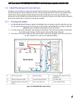
Cable Routing and Connection
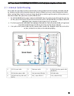
All cables in the system that need to be routed from front to back, should be routed using the cable
channels along each chassis sidewall as shown in the following illustration. When routing cables from
front to back, none should be routed through the center of the system or in the area between the
system fans and the DIMM slots. Cable connection instructions provided in this section are presented in
the recommended order in which they should be installed.
1.3.1
Routing the Cables
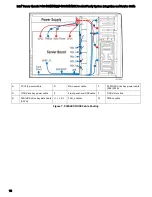
1.
For P4304XXMFEN2, the power cables for HDD/ODD bays should be routed through the opening
on the system fan bracket, close to the chassis side wall; for P4304XXMUXX, the power cables for
HDD/ODD bays should be routed under the 5
th
system fan.
2.
The front panel cable, SATA/SAS data cable(s), USB cable (to the front panel), HSBP_I2C (optional)
should be routed between the first system fan and the chassis sidewall.
3.
The system main power cable and CPU power cables need to be managed under the notch of the
air duct, before the air duct can be installed properly.
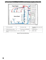
A
CPU1/2 power cable
B
Main power cable
C
SSD/HDD drive bay power cable
(SAS/SATA)
D
ODD drive bay power cable
E
Front panel and USB cable
F
ODD data cable
G
SSD/HDD drive bay data cable
(SATA)
H
FAN_1 cable (PCIe fan)
I
FAN_2 cable (CPU fan)
Figure 6. P4304XXMFEN2 Cable Routing


