


Customer Services (858) 578-7887 & (888) GO IN
TEC
IN
TEC
Controls, 12700 Stowe Dr., Suite 1
0
0, Poway, CA 92064
Fax (858) 578-4633 & (888) FX IN
TEC
www.inteccontrols.com
Specification subject to change without notice.
Printed in USA 131119
Polygard® is a registered trademark of MSR
LGC/LG2-04
PolyGard
®
Multi-Point Controller
User Manual - LGC/LG2-04
Page 27
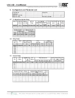
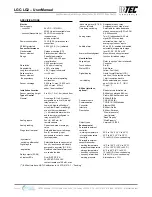
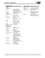
7 Specifications LGC/LG2-04
Specifications subject to change without notice. | USA 131119 | Page 27 of 30
12700 Stowe Drive, Suite 100, Poway, CA 92064 | Ph: (858) 578.7887 & (888) GO.IN
TEC
| relevantsolutions.com/inteccontrols
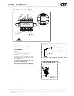
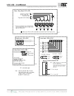
LGC-LG2 – UserManual
Polygard® is a registered trademark of MSR | LGC/LG2-04
Specifications subject to change without notice. | USA 160104 | Page 27 of 30
12700 Stowe Drive, Suite 100, Poway, CA 92064 | Ph: (858) 578.7887 & (888) GO.IN
TEC
| relevantsolutions.com/inteccontrols
LGC-LG2 – UserManual
PolyGard
®
is a registered trademark of MSR-Electronic GmbH | LGC/LG2-04
Specifications subject to change without notice. | USA 140924 | Page 1 of 6
INTEC Controls | 12700 Stowe Drive, Suite 100, Poway, CA 92064 | Ph: (858) 578.7887 & (888) GO.INTEC | inteccontrols.com
Carbon Monoxide (CO) Gas Detection and Control System
DESCRIPTION
Carbon monoxide (CO) detection and control system, wall-mounted, with
one, two, three or four remote sensors/transmitters.
APPLICATION
To detect and control levels of carbon monoxide (CO) in a wide variety of
commercial and industrial applications such as vehicle exhaust in parking
structures, engine repair shops, equipment rooms and ventilation systems,
etc. The controller can interface via binary outputs and up to (2) 4-20 mA
signals with any compatible electronic analog control, DDC/PLC control or
automation system.
FEATURES
•
Continuous monitoring
• CO electrochemical sensor,
gas specific
• Polarity protected
• Up to (4) sensor inputs
• Four (4) digital inputs
• Five (5) relay outputs:
- Five-stage control
- Fail-safe assignable
• Two (2) analog outputs, 4-20 mA
- Selectable for low, high or averaging
• Optional BACnet coupler upwards
communication to BAS
• Liquid Crystal Display (LCD)
PolyGard
LGC-CO
• LED status indicators
• Built-in horn
• Keypad user interface
• Simple menu-driven
programming
• RFI/EMI protected
• Modular plug-in technology
• Overload & short-circuit
protected
• NEMA 4X, transmitter
enclosure
• NEMA 4X, controller
enclosure
• Easy maintenance
ORDERING INFORMATION
Upwards Communication Options
BACnet
NRTL Performance Tested & Certified
Conforms to STD
UL 2075
/
UL 2017
City of Los Angeles Approved
Carbon Monoxide (CO) Detection and Control System Package
Controller
Sensor(s) / Transmitter(s)
Part Numbers
Digital programmable menu-driven
keypad user interface LCD & LEDs,
24 VDC, NEMA 4X enclosure
Inputs: (4) 4-20 mA
Outputs: (5) Relays, SPDT, 8 A
(2) 4-20 mA
Built-in (1) Horn
Sensor range:
0-250 ppm CO,
4-20 mA, 2-wire,
loop powered 24 VDC,
NEMA 4X wall mount
enclosure
Incl. (1) CO remote
sensor
LGC-CO-01
Incl. (2) CO remote
sensors
LGC-CO-02
Incl. (3) CO remote
sensors
LGC-CO-03
Incl. (4) CO remote
sensors
LGC-CO-04
BACnet upwards communication coupler “T5-BAC-1-A” (external)
T5-BAC-1-A
Factory configured CO alarm levels/setpoints:
• Low alarm @ 25 ppm (relay #01)
• Horn alarm @ 100 ppm (relay #05)
• High alarm @ 100 ppm (relay #02)
Other setpoints/programming are available on special request.
All devices are field programmable and adjustable.
INTEC Controls | 12700 Stowe Drive, Suite 100, Poway, CA 92064 | Ph: (858) 578.7887 & (888) GO.INTEC | inteccontrols.com
Specifications subject to change without notice. | USA 200211 | Page 27 of 30
LGC-LG2 – UserManual


