12
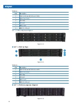
Table 3-2
Item
Description
1
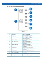
Front control panel buttons and LEDs
2
Quick release lever
3
Drive bays
4
VGA port
5
USB3.0 port
6
USB2.0 + LCD port
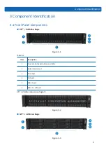
3.5” × 12 drive sequence diagram
Figure 3-4
●
2.5” × 25 Drive Bays
9
Component Identification
3 Component Identification
3.1 Front Panel Components
●
2.5”
×
24 HDD Bays
Item
Description
1
Front control panel buttons and LEDs
2
Quick release lever
3
HDD bays
4
VGA port
5
USB3.0 port
6
USB2.0 + LCD port
2.5” × 24 HDD sequence diagram
●
3.5” × 12 HDD Bays
Figure 3-5
Table 3-3
Item
Description
1
Front control panel buttons and LEDs
2
Quick release lever
3
Drive bays
4
VGA port
5
USB3.0 port
6
USB2.0 + LCD port
●
2.5” × 25 drive sequence diagram
0
5
10
15
20
1
6
11
16
21
2
7
12
17
22
3
8
13
18
23
4
9
14
19
24
Figure 3-
6


