background image

Parameter Description                                                                                     MD320/MD320N User Manual                                                 

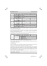
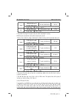
F2-08

Torque control

Factory default value

0

Setup range 

0

Inactive 

1

Enabled 

,QWKHYHFWRUFRQWUROPRGHWKHRXWSXWRIVSHHGORRSUHJXODWRULVWRUTXHFXUUHQWFRPPDQG7KLV
SDUDPHWHULVXVHGWR¿OWHUWKHWRUTXHFRPPDQG7KLVSDUDPHWHUQHHGVQRDGMXVWPHQWJHQHUDOO\
DQGWKLV¿OWHUWLPHFDQEHLQFUHDVHGLQFDVHRIKXJHVSHHGÀXFWXDWLRQ,QFDVHRIRVFLOODWLRQRI
PRWRUWKLVSDUDPHWHUVKDOOEHUHGXFHGSURSHUO\

7KHWLPHFRQVWDQWRIVSHHGORRS¿OWHULVORZDQGWKHRXWSXWWRUTXHRIWKHLQYHUWHUPD\YDU\
JUHDWO\EXWWKHUHVSRQVHLVTXLFN

7RUTXHFRQWUROLVLQDFWLYHDQGWKHLQYHUWHUSHUIRUPVFRPPDQGVSHHGFRQWURO,QFDVHRI
VSHHGFRQWUROWKHLQYHUWHURXWSXWVIUHTXHQF\LQDFFRUGDQFHZLWKWKHVHWXSIUHTXHQF\FRPPDQG
DQGWKHRXWSXWWRUTXHDXWRPDWLFDOO\PDWFKHVWKHORDGWRUTXHEXWWKHRXWSXWWRUTXHLVOLPLWHGE\

the torque upper limit (refer to F2-09 and F2-10). When the load torque is higher than the setup 

WRUTXHXSSHUOLPLWWKHRXWSXWWRUTXHRIWKHLQYHUWHULVOLPLWHGDQGWKHRXWSXWIUHTXHQF\ZLOOEH

different from the setup frequency. 

7RUTXHFRQWUROLVHQDEOHGDQGWKHLQYHUWHUSHUIRUPVWRUTXHFRQWURO,QFDVHRIWRUTXHFRQWURO
WKHLQYHUWHURXWSXWVWRUTXHLQDFFRUGDQFHZLWKWKHVHWXSWRUTXHFRPPDQGDQGWKHRXWSXW
IUHTXHQF\DXWRPDWLFDOO\PDWFKHVWKHORDGVSHHGEXWWKHRXWSXWIUHTXHQF\LVOLPLWHGE\WKH

frequency upper limit (refer to F0-12). When the load speed is higher than the setup frequency 

XSSHUOLPLWWKHRXWSXWIUHTXHQF\RIWKHLQYHUWHULVOLPLWHGDQGWKHRXWSXWWRUTXHZLOOEHGLIIHUHQW

from the setup torque. 

,QFDVHRIWRUTXHFRQWUROWKHWRUTXHFRPPDQGLVWKHWRUTXHXSSHUOLPLWDQGVHWE\WKHWRUTXH

upper limit source (F2-09). 

It can perform switching between torque control and speed control via the multifunctional input 
terminals. 

,QFDVHRIWRUTXHFRQWUROWKHRXWSXWIUHTXHQF\RIWKHLQYHUWHUDXWRPDWLFDOO\WUDFNVWKHFKDQJH
RIWKHORDGVSHHGEXWWKHFKDQJHRIWKHRXWSXWIUHTXHQF\LVDIIHFWHGE\WKHVHWXSDFFHOHUDWLRQ
GHFHOHUDWLRQWLPH,ILWQHHGVWRTXLFNHQWKHWUDFNLQJVSHHGWKHDFFHOHUDWLRQGHFHOHUDWLRQWLPH

shall be shortened. 

:KHQWKHVHWXSWRUTXHRIWKHLQYHUWHULVKLJKHUWKDQWKHORDGWRUTXHWKHRXWSXWIUHTXHQF\RIWKH
LQYHUWHUZLOOULVHZKHQWKHRXWSXWIUHTXHQF\RIWKHLQYHUWHUUHDFKHVWKHIUHTXHQF\XSSHUOLPLW

the inverter will keep running with the frequency upper limit. 

:KHQWKHVHWXSWRUTXHRIWKHLQYHUWHULVORZHUWKDQWKHORDGWRUTXHWKHRXWSXWIUHTXHQF\RIWKH
LQYHUWHUZLOOIDOOZKHQWKHRXWSXWIUHTXHQF\RIWKHLQYHUWHUUHDFKHVWKHIUHTXHQF\ORZHUOLPLWWKH

inverter will keep running with the frequency lower limit. 


efesotomasyon.com

Summary of Contents for MD320 Series

Page 1: ...RQ PRGL FDWLRQ VSHFL FDWLRQ PRGL FDWLRQ z I RX ZDQW WR RUGHU WKH PDQXDO GXH WR ORVV RU GDPDJH SOHDVH FRQWDFW RXU company agents in each region or our company customer service center directly z I WKHUH...

Page 2: ...tion of inverter Refer to Figure 1 for the comparison between traditional inverter and MD series modular inverter 2 It creates the physical standard for dividing the customer requirements according to...

Page 3: ...D300 functional module Refer to Table 1 for the difference between the two modules Table 1 Difference between MD320 and MD300 Functional Modules MD320 MD300 Input output terminal Five DI bidirectional...

Page 4: ...rminal and DC powered fan that enable the standard products WR EH FRPSDWLEOH ZLWK WKH EXV UXQQLQJ PRGH SHUIHFW XVHU SDVVZRUG SURWHFWLRQ VKRUWFXW PHQX GHVLJQ WKDW PDNHV WKH FRPSOH FRPPLVVLRQ HDVLHU VWD...

Page 5: ...QJ 0HWKRG for the Product Comply with IEC EN61800 3 standard under correct installation and use as per Article 7 3 2 and 7 3 6 MD320N MD320N series is an upgrade of the MD320 series in terms of extern...

Page 6: ...ping Guide 37 2 10 Guide to Prototyping of Brake Components 37 Chapter 3 Mechanical and Electric Installation 42 3 1 Mechanical installation 42 OHFWULFDO QVWDOODWLRQ Chapter 4 Operation and Display 60...

Page 7: ...KDSWHU 0 OHFWURPDJQHWLF RPSDWLELOLW H QLWLRQ 0 6WDQGDUG HVFULSWLRQ 0 XLGH Chapter 8 Fault Diagnosis and Solution 160 8 1 Fault Alarm and Countermeasures 160 8 2 Common Fault and Resolution 173 Append...

Page 8: ...r Electromagnetic Contactor AC Reactor Electromagnetic Contactor Brake Resistors Optional UDNH 8QLW RU QHUJ HHGEDFN 8QLW Optional DC Reactor standard configuration 7R LQVXUH WKH VDIHW SOHDVH XVH HOHFW...

Page 9: ...z G Gw efesotomasyon com...

Page 10: ...o do with the company 1 1 Safety precautions 1 1 1 Before Installation 1 1 2 During the Installation Danger z R QRW XVH WKH GDPDJHG LQYHUWHU RU LQYHUWHU ZLWK PLVVLQJ SDUWV 2WKHUZLVH there may be risk...

Page 11: ...be danger of electric shock z There shall be circuit breaker between the inverter and power supply 2WKHUZLVH WKHUH PD EH UH z Make sure the power is disconnected prior to the connection Otherwise ther...

Page 12: ...H danger of injury arising from the rotating motor Otherwise accident may occur z Do not change the factory settings at will Otherwise it may damage the equipment Caution z 3OHDVH FRQ UP ZKHWKHU WKH S...

Page 13: ...VH RX PD JHW EXUQW z Detection of signals during the operation shall only be conducted by TXDOL HG WHFKQLFLDQ 2WKHUZLVH SHUVRQDO LQMXU RU HTXLSPHQW GDPDJH PD be caused Caution z XULQJ WKH RSHUDWLRQ RI...

Page 14: ...QYHUWHU W LV recommended that such devices not be used I D FRQWDFWRU LV LQVWDOOHG EHWZHHQ WKH SRZHU VXSSO DQG WKH LQSXW WHUPLQDO RI WKH LQYHUWHU LW is not allowed to use the contactor to control the s...

Page 15: ...tes 1 The standard adaptable motor is four pole squirrel cage asynchronous induction motor If VXFK PRWRU LV QRW DYDLODEOH EH VXUH WR VHOHFW DGDSWDEOH PRWRUV LQ DFFRUGLQJ WR WKH UDWHG FXUUHQW RI WKH PR...

Page 16: ...Safety and Precautions MD320 MD320N User Manual efesotomasyon com...

Page 17: ...w Gp efesotomasyon com...

Page 18: ...e UDNH 8QLW B QFOXGLQJ UDNH 8QLW G Gerneral Type Model P Fan Pump Type Fig 2 1 Designation Rules Fig 2 2 Nameplate Caution The MD320N series is an upgrade of the MD320 series in terms of external DSSH...

Page 19: ...16 3 0 14 0 7 0 2 MD320NS2 2 4 0 23 0 9 6 2 2 3 Three phase power supply 380 480V MD320NT0 7 3 4 2 1 1 0 17 3 0 3 8 2 MD320NT2 2 4 0 2 2 3 MD320NT3 7 9 0 3 7 0 17 8 9 14 6 13 0 0 17 11 0 17 0 10 MD320...

Page 20: ...80 0 430 0 426 0 220 0 17 468 0 400 MD320NT280 396 0 280 0 17 0 17 MD320NT400 400 0 600 0 17 630 0 883 0 820 0 Three phase Power supply 690V MD320 7T132 192 0 170 0 132 200 MD320 7T160 231 0 200 0 160...

Page 21: ...30 0 V F curve 7KUHH W SHV VWUDLJKW OLQH PXOWLSOH SRLQW DQG VTXDUH W SH Speed up and Speed down curve Straight line or S curve speed up and speed down mode four kinds of speed up and speed down time s...

Page 22: ...HQFH DQDORJ FXUUHQW UHIHUHQFH SXOVH UHIHUHQFH DQG VHULDO SRUW UHIHUHQFH 7KHVH frequency sources can be switched in various modes Auxiliary frequency source There are ten types of auxiliary frequency s...

Page 23: ...FXUUHQW SURWHFWLRQ RYHU YROWDJH SURWHFWLRQ XQGHU YROWDJH SURWHFWLRQ RYHU KHDW protection and overload protection Optional parts RSHUDWLRQ SDQHO PXOWLIXQFWLRQDO 2 H SDQVLRQ FDUG EUDNLQJ FRPSRQHQWV FRP...

Page 24: ...Product Information MD320 MD320N User Manual Fig 2 4 Physical Appearance of Inverter LJ 6FKHPDWLF LDJUDP IRU 3K VLFDO LPHQVLRQV DQG 0RXQWLQJ LPHQVLRQV RI N N efesotomasyon com...

Page 25: ...0 MD320N User Manual Product Information LJ 6FKHPDWLF LDJUDP IRU 3K VLFDO LPHQVLRQV DQG 0RXQWLQJ LPHQVLRQV RI N N LJ 6FKHPDWLF LDJUDP IRU 3K VLFDO LPHQVLRQV DQG 0RXQWLQJ LPHQVLRQV RI N N efesotomasyon...

Page 26: ...m Model Mounting Hole mm Physical Dimensions mm Diameter of Mounting Hole mm Weight kg A B H H1 W D MD320S0 4G 113 172 182 123 1 1 MD320S0 7G 0 6 MD320S2 2G MD320T0 7GB 0 7 MD320T2 2GB MD320T2 2GB Bui...

Page 27: ...3 0 7 0 7 3 0 7 MD320T22P 447 430 460 220 20 MD320T22G MD320T30P MD320T30G MD320T37P MD320T37G 0 7 3 620 380 262 34 0 7 0 7 3 0 7 0 7 3 0 7 MD320T90P 343 678 660 700 473 307 47 MD320T90G MD320T110P MD...

Page 28: ...92 440 310 90 MD320 7T160GH MD320 7T200PH MD320 7T200GH MD320 7T220PH MD320 7T220GH 0 7 3 0 7 MD320 7T280PH MD320 7T280G 0 7 3 420 1030 983 1060 377 130 0 7 0 7 3 0 7 MD320 7T400P MD320 7T400G 0 7 3 1...

Page 29: ...7G 0 16 MD320NS2 2G MD320NT0 7GB 0 17 MD320NT2 2GB MD320NT3 7GB 148 236 248 160 183 0 17 3 0 17 0 17 3 0 17 190 322 208 192 6 MD320NT11PB MD320NT11GB 0 17 3 0 17 0 17 3 0 17 MD320NT22P 447 432 463 228...

Page 30: ...8 660 700 473 307 10 47 MD320NT90P MD320NT90G MD320NT110P MD320NT110G 449 903 880 930 380 10 90 MD320NT132P MD320NT132G MD320NT160P MD320NT160G MD320NT200P 420 1030 983 1060 377 12 130 MD320NT200G MD3...

Page 31: ...rnal Keyboard Fig 2 9 Schematic Diagram for Physical Dimensions of External Keyboard Mounting Hole Dimensions of External Keyboard Fig 2 10 Schematic Diagram for Mounting Hole Dimensions of External K...

Page 32: ...oles Connection Diameter Hole of the copper medal 0 7 3 90G 110P 110G 132P 160 190 161 192 12 MD320T132G 160P 160G 160 190 161 192 12 MD320T200P 200G 3 3 190 230 93 128 200 13 18 0 7 3 3 190 230 93 12...

Page 33: ...optional water supply modes as well as standby function DQG UH FRQWURO IXQFWLRQ Built in clock I O expansion card MD32IO W FDQ DGG ILYH GLJLWDO LQSXWV RQH DQDORJ YROWDJH LQSXW RQH UHOD RXWSXW RQH GLJL...

Page 34: ...ay and operation keyboard 5 LQWHUIDFH Parameter copy unit MDCP Parameter copy MD series general SXUSRVH 5 interface EPS commercial power synchronization card MD32EPS EPS mains synchronization The outp...

Page 35: ...The inverter shall be kept clean all the time 7KH GXVW RQ WKH VXUIDFH RI WKH LQYHUWHU VKDOO EH HIIHFWLYHO UHPRYHG VR DV WR SUHYHQW WKH GXVW entering the inverter Especially the metal dust is not allow...

Page 36: ...QG ZKHWKHU WKH VDIH YDOYH KDV SURMHFWHG DQG PHDVXUH WKH VWDWLF FDSDFLWDQFH DQG WKH LQVXODWLQJ UHVLVWDQFH 2 7 4 Storage of Inverter 8SRQ DFTXLULQJ WKH LQYHUWHU WKH XVHU VKDOO SD DWWHQWLRQ WR WKH IROORZ...

Page 37: ...DQG G QDPLF SHUIRUPDQFH DUH ORZ WUXGLQJ PDFKLQH DJLWDWRU EHOW FRQYH HU WUDQVSRUWLQJ WUROOH LQ WKH IDFWRU DQG WUDQVODWLRQDO XQLW RI FUDQH DUH WKH H DPSOHV W can select MS V F running mode when performi...

Page 38: ...IUHTXHQF RI HOHYDWRU LV EHWZHHQ a WKH ZLQGLQJ DQG XQZLQGLQJ LV EHWZHHQ a 7KH FHQWULIXJH LV EHWZHHQ a 2FFDVLRQDO EUDNH ORDG LV 7KH HQHUDO VHOHFWLRQ LV Table 2 7 MD320 Inverter Bake Components Prototypi...

Page 39: ...8 MD320T90 N Externally connected 0 8 MD320T110 N Externally connected 0 8 MD320T132 N Externally connected 0 8 MD320T160 16kW Externally connected 0 8 MD320T200 20 kW Externally connected 0 8 MD320T2...

Page 40: ...Product Information MD320 MD320N User Manual efesotomasyon com...

Page 41: ...t G Gl Gp efesotomasyon com...

Page 42: ...r shall be mounted in the place without vibration or with vibration of less than DQG VKDOO EH NHSW DZD IURP VXFK HTXLSPHQW DV SXQFKLQJ PDFKLQH 7KH LQYHUWHU VKDOO EH PRXQWHG LQ ORFDWLRQV IUHH IURP GLUH...

Page 43: ...and install an insulating splitter 2 7KH PRXQWLQJ VSDFH VKDOO EH DV LQGLFDWHG DV WKH DERYH JXUH VR DV WR HQVXUH WKH KHDW GLVVLSDWLRQ VSDFH RI WKH LQYHUWHU RZHYHU WKH KHDW GLVVLSDWLRQ RI RWKHU GHYLFHV...

Page 44: ...H 3OHDVH UHIHU WR Figure 3 4 for removing the lower cover plate of the sheet metal enclosure It is easy to loosen the screws of the upper cover plate with tools Danger z KHQ UHPRYLQJ WKH GRZQ FRYHU SO...

Page 45: ...he Input Side mm Recomm ended Conducting Wire of Main Circuit at the Output Side mm Recomme nded Conducting Wire of Control Circuit mm MD320S0 4G 16 10 1 0 MD320S0 7G 16 10 1 0 0 6 20 16 4 0 1 0 MD320...

Page 46: ...160G 200P 400 MD320T200G 220P 600 600 0 7 3 600 600 0 7 3 800 600 0 7 3 800 800 0 7 3 800 800 0 7 3 800 800 0 7 3 1000 1000 MD320 7T Refer to parameters of rated current of 380V system alike Caution T...

Page 47: ...ctor of PRUH WKDQ DV standard Improve the power factor of the input side Improve the whole efficiency and thermal stability of the inverter Eliminate the impact of higher harmonics of the input side o...

Page 48: ...ollowed the product model represents Self braking unit 4 Braking resistor s selection is based on the user demand See the prototyping Guide of braking resistor for details 6LJQDO OLQHV DQG SRZHU OLQH...

Page 49: ...l refers to the main circuit terminal 7HUPLQDO UHIHUV WR WKH FRQWURO FLUFXLW WHUPLQDO 7KH N a N XWR XQLW LV WKH VWDQGDUG FRQ JXUDWLRQ N a N LV EXLOG LQ UHDFWRU 4 The selection of the braking resistor...

Page 50: ...e of the input power supply is consistent with that of the inverter Otherwise it may damage the inverter 2 Make sure that the motor matches the inverter Otherwise it may damage the motor or generate i...

Page 51: ...cuit power terminal Terminals Name Description L1 L2 Input terminal of single phase power supply single phase 220V power connection point Negative and positive terminals of DC bus Shared DC Bus input...

Page 52: ...at the voltage is less than 36V prior to wiring connection Otherwise there may be danger of electric shock KHQ VHOHFWLQJ H WHUQDO EUDNH XQLW IRU WKH LQYHUWHU RI PRUH WKDQ N WKH SROHV RI DQG VKDOO QRW...

Page 53: ...ontrol terminal and connection 1 Control terminals and connection Fig 3 8 Layout of Control Circuit Terminals 2 Function description of control terminal Table 3 3 Description of Control Terminal Funct...

Page 54: ...so be used as the high speed pulse input channel 0D LPXP LQSXW IUHTXHQF LV N Analog Output AO1 GND Analog output 1 The voltage or current output is determined by WKH MXPSHU RQ WKH FRQWURO ERDUG Output...

Page 55: ...rameter copy unit interface 3 Description of Connection of control terminals A Analog input terminal 6LQFH WKH ZHDN DQDORJ YROWDJH VLJQDO LV HDV WR VXIIHU H WHUQDO LQWHUIHUHQFHV LW QHHGV WR HPSOR VKLH...

Page 56: ...ed to use the contact control mode C DI Terminal Connection 1 Connection with dry contact sharing the negative pole Inverter Control Board Fig 3 11 Connection with dry contact sharing the negative pol...

Page 57: ...W FLUFXLW FRSSHU EDU EHWZHHQ 9 DQG 23 DQG WKHQ FRQQHFW 23 ZLWK 0 I H WHUQDO SRZHU VXSSO LV XVHG LW PXVW DOVR UHPRYH WKH VKRUW circuit copper bar between CME and COM 3 Source Electrode Connection Exter...

Page 58: ...QG 23 DQG connect OP with the public tend of the external controller and OP with CME If external power VXSSO LV XVHG LW PXVW DOVR UHPRYH WKH VKRUW FLUFXLW FRSSHU EDU EHWZHHQ 0 DQG 20 D Digital output...

Page 59: ...v G Gk efesotomasyon com...

Page 60: ...n status 2 5 027 W LV WKH LQGLFWRU IRU NH ERDUG RSHUDWLRQ WHUPLQDO RSHUDWLRQ DQG UHPRWH RSHUDWLRQ FRPPXQLFDWLRQ FRQWURO KHQ LW LV 2 LW LQGLFDWHV WKH NH ERDUG RSHUDWLRQ FRQWURO VWDWXV ZKHQ LW LV 21 LW...

Page 61: ...y LQWHUIDFH DQG UXQQLQJ GLVSOD LQWHUIDFH DQG VHOHFW WKH PRGL FDWLRQ GLJLW RI SDUDPHWHUV ZKHQ PRGLI LQJ SDUDPHWHUV RUN Running key It is used to start the running of the inverter under keyboard control...

Page 62: ...3 Shortcut Menu Operation Mode The shortcut menu is set to facilitate the user to quickly view and modify the commonly used IXQFWLRQ SDUDPHWHUV Q WKH VKRUWFXW PHQX WKH SDUDPHWHU LV GLVSOD HG LQ WKH I...

Page 63: ...shortcut menu in accordance with the actual needs Fig 4 4 Example of Adding Shortcut Parameter Item DXWLRQ KHQ SUHVVLQJ 48 NH GXULQJ WKH SURJUDPPLQJ RI OHYHO PHQX WKH GLVSOD flashes and prompts wheth...

Page 64: ...me as that 4 5 Method of Viewing Status Parameter Q VWRS RU UXQQLQJ VWDWXV LW FDQ GLVSOD PXOWLSOH VWDWXV SDUDPHWHUV W FDQ VHOHFW ZKHWKHU WR GLVSOD WKH SDUDPHWHU WKURXJK WKH IXQFWLRQ FRGHV UXQQLQJ SDUD...

Page 65: ...t standard motor parameters matching the nameplate parameter Since the vector control mode relies highly RQ WKH PRWRU SDUDPHWHUV LW PXVW DFTXLUH WKH DFFXUDWH SDUDPHWHUV RI WKH FRQWUROOHG PRWRU WR ensu...

Page 66: ...d no load current of WKH PRWRU ZKLFK FDQ EH FDOFXODWHG E WKH XVHU EDVHG RQ WKH PRWRU QDPHSODWH 7KH PRWRU QDPHSODWH SDUDPHWHUV XVHG LQ WKH FDOFXODWLRQ LQFOXGH UDWHG YROWDJH 8 UDWHG FXUUHQW O UDWHG IUHT...

Page 67: ...m Gw G efesotomasyon com...

Page 68: ...e from password protection The symbols in the function table are described as follows W LQGLFDWHV WKDW WKH SDUDPHWHU VHWXS YDOXH FDQ EH PRGL HG ZKHQ WKH LQYHUWHU LV LQ VWRS status and running status W...

Page 69: ...ce selection Command source selection 0 Operation panel running command channel LED OFF 1 Terminal command channel LED ON 2 serial port command channel DVKHV 1 0 F0 03 Main frequency source X selectio...

Page 70: ...y source Y 4 Switching between main frequency source Y and main f r e q u e n c y s o u r c e X p l u s auxiliary frequency source Y 1 0 F0 08 Preset frequency Preset frequency a PD LPXP IUHTXHQF F0 1...

Page 71: ...ynchronous motor 1 Variable frequency asynchronous motor 2 Permanent magnetic synchronous motor 1 0 F1 01 rated power rated power 0 4kW 1000 0kW 0 1kW Model dependent F1 02 rated voltage rated voltage...

Page 72: ...Speed loop l2 0 01s 10 00s 0 01s 1 00s switching frequency 2 2 switching frequency 2 F2 02 Max frequency 0 01Hz 10 00Hz F2 06 Slip compensation FRHI FLHQW 6OLS FRHI FLHQW 200 1 100 F2 07 Time constan...

Page 73: ...DWHG PRWRU IUHTXHQF 0 01Hz 0 00Hz F3 04 V F voltage point 1 V F voltage 1 0 0 100 0 0 1 0 0 V F frequency point 2 V F frequency 2 a UDWHG PRWRU IUHTXHQF 0 01Hz 0 00Hz F3 06 V F voltage point 2 V F vol...

Page 74: ...n selection terminal 1 17 Speed up Speed down selection terminal 2 18 Main frequency source switching 83 DQG 2 1 VHWXS FOHDU terminal and keyboard 1 1 F4 01 DI2 terminal function selection DI2 termina...

Page 75: ...n c y s e t u p e n a b l e d terminal this terminal is enabled by default If this terminal IXQFWLRQ LV VHW WKH HQDEOLQJ time of modification will be controlled by this enabled t e r m i n a l w h e n...

Page 76: ...he frequency source y can be replaced with preset frequency F0 08 F4 10 DI terminal OWHU WLPH OWHU WLPH 1 10 1 4 F4 11 Terminal command mode Terminal command mode 0 Two line mode 1 1 Two line mode 2 2...

Page 77: ...OWHU WLPH 0 00s 10 00s 0 01s 0 10s F4 23 AI3 minimum input on IO expansion card AI3 minimum input 0 00V 10 00V 0 01V 0 00V F4 24 AI3 minimum input correspondi ng setup on IO expansion card AI3 minimu...

Page 78: ...0 100 0 0 1 0 0 F4 30 38 6 pulse input maximum frequency Pulse maximum frequency 0 00kHz N 0 01 kHz N F4 31 38 6 pulse input maximum frequency corresponding setup Pulse maximum setup 100 0 100 0 0 1...

Page 79: ...al 8QGHU YROWDJH VWDWXV RXWSXW 20 communication reference 1 0 Control board relay T A T B T C output selection Control board RELAY1 output selection 1 2 selection of expansion card RELAY P A P B P C s...

Page 80: ...02 Rotation speed tracking speed Rotation speed tracking speed 1 100 1 20 F6 03 Start frequency Start frequency 0 00 Hz 10 00Hz 0 01Hz 0 00Hz F6 04 Start frequency holding time Start holding time 0 0s...

Page 81: ...on panel command channel and r e m o t e c o m m a n d c h a n n e l terminal command channel or serial port communication command channel 2 Switching between forward rotation and reverse rotation RUZ...

Page 82: ...J VSHHG down time 0 0s V 0 1s 20 0s F8 03 Speed up time 2 Speed up time 2 0 0s V 0 1s 20 0s F8 04 Speed down time 2 Speed down time 2 0 0s V 0 1s 20 0s Speed up time 3 Speed up time 3 0 0s V 0 1s 20 0...

Page 83: ...8 18 Start protection selection Start protection selection 0 No protection 1 Protection 1 0 F8 19 Frequency detection value FDTlevel FDT level a PD LPXP IUHTXHQF 0 01Hz F8 20 Frequency detection hyste...

Page 84: ...nt Stall gain over current 0 100 1 20 F9 06 Stall protection current over current Stall point over current 100 200 1 F9 07 Transient stop non stop function Transient stop non stop function 0 Inactive...

Page 85: ...ERR07 8 C o n t r o l p o w e r s u p p l y fault ERR08 8QGHU YROWDJH IDLOXUH 55 10 Inverter overload ERR10 11 Motor overload ERR11 12 Input phase failure ERR12 13 Output phase failure ERR13 14 Radiat...

Page 86: ...03 PID action direction PID action direction 0 Positive action 1 Reverse action 1 0 FA 04 PID setup feedback range PID range 0 1 1000 Proportional gain P Proportional gain P 0 0 100 0 0 1 20 0 FA 06 I...

Page 87: ...09 Designated counting value Designated counting value 1 1 1000 Group FC MS speed and PLC FC 00 MS speed 0 MS speed 0 Negative maximum frequency to maximum frequency 0 1Hz 0 0Hz FC 01 MS seed 1 MS see...

Page 88: ...quency to maximum frequency 0 1Hz 0 0Hz 06 VSHHG 06 VSHHG Negative maximum frequency to maximum frequency 0 1Hz 0 0Hz FC 16 PLC running mode PLC mode 0 Stop upon completion HHS QDO YDOXH XSRQ completi...

Page 89: ...ent running time of PLC Forth segment time 0 0s h V K 0 1s h 0 0s h FC 27 Forth segment speed up speed down time selection of PLC Four segment speed up speed down 0 3 1 0 FC 28 Fifth segment running t...

Page 90: ...speed down time selection of PLC Eighth segment speed up speed down 0 3 1 0 FC 36 Ninth segment running time of PLC Ninth segment time 0 0s h V K 0 1s h 0 0s h FC 37 Ninth segment speed up speed down...

Page 91: ...0 3 1 0 FC 44 Thirteenth segment running time of PLC Thirteenth segment time 0 0s h V K 0 1s h 0 0s h Thirteenth segment speed up speed down time selection of PLC Thirteenth segment speed up speed do...

Page 92: ...address WR DQG LV WKH EURDGFDVW address 1 1 FD 03 response delay response delay 0ms 20ms 1 2 FD 04 Communi cation timeout time Communi cation timeout time LQDFWLYH DQG a V 0 1s 0 0 communi cation pro...

Page 93: ...w Gk efesotomasyon com...

Page 94: ...O FHQWULIXJDO PDFKLQH ZLUH GUDZLQJ PDFKLQH DQG LQMHFWLRQ molding machine 1 Speed sensor vector control refers to close loop vector It must be added with encoder and PG card and is applicable to the ap...

Page 95: ...X selection Factory default value 0 Setup Range 0 LJLWDO VHWXS 83 DQG 2 1 QRQ UHFRUGHG 1 LJLWDO VHWXS 83 DQG 2 1 UHFRUGHG 2 AI1 3 AI2 4 AI3 38 6 VHWXS O 6 MS speed 7 PLC 8 PID 9 Communication setup Se...

Page 96: ...SHFL FDWLRQ YROWDJH UDQJH RI 9 WR 9 DQG IUHTXHQF UDQJH RI N WR N DXWLRQ 3XOVH JLYHQ FDQ RQO EH LQSXW IURP WKH PXOWLIXQFWLRQDO LQSXW WHUPLQDO 6 MS speed Select MS speed running mode It needs to set Gro...

Page 97: ...QF VRXUFH UDQJH UHIHU WR DQG 7R DGMXVW WKH PDLQ UHIHUHQFH IUHTXHQF LW QHHGV WR VHW WKH FRUUHVSRQGLQJ setup range of analog input to n to n refer to F4 13 and F4 26 KHQ WKH IUHTXHQF VRXUFH LV SXOVH LQS...

Page 98: ...equency source Y KHQ LV VHOHFWHG WKH IUHTXHQF VRXUFH PDLQ IUHTXHQF VRXUFH SOXV DX LOLDU IUHTXHQF source Y can realize frequency overlapping function KHQ LV VHOHFWHG LW FDQ VZLWFK EHWZHHQ WKH PDLQ IUHT...

Page 99: ...ue Setup Range WR F0 11 Frequency source upper limit Factory default value 0 Setup Range 0 F0 12 setup 1 AI1 2 AI2 3 AI3 4 38 6 VHWXS Communication setup It is used to define the source of frequency u...

Page 100: ...UHQW WR WKH HDUWK DQG WKH LQWHUIHUHQFH RI WKH LQYHUWHU FDQ EH reduced KHQ WKH FDUULHU IUHTXHQF LV ORZ WKH RXWSXW FXUUHQW KLJKHU KDUPRQLF FRPSRQHQW ZLOO LQFUHDVH WKH PRWRU ORVV ZLOO LQFUHDVH DQG WKH PR...

Page 101: ...the maximum output frequency F0 10 Speed down time 1 refers to the time t2 required for the inverter to Speed down from the PD LPXP RXWSXW IUHTXHQF WR DV VKRZQ LQ WKH IROORZLQJ JXUH Setting Frequency...

Page 102: ...ange 9a 9 F1 03 Rated current Factory default value model dependent Setup range a F1 04 Rated Frequentcy Factory default value model dependent Setup range a PD LPXP IUHTXHQF F1 05 Rated rotation speed...

Page 103: ...SHUIRUPDQFH RI WKH LQYHUWHU SOHDVH VHOHFW URWDU WXQLQJ XULQJ WKH URWDU WXQLQJ WKH PRWRU PXVW EH GLVFRQQHFWHG ZLWK WKH ORDGV L H QR ORDG 8SRQ VHOHFWLRQ RI URWDU WXQLQJ WKH LQYHUWHU ZLOO FRQGXFW VWDWLF...

Page 104: ...dopt the factory default value F2 00 Speed loop proportional gain 1 Factory default value 30 Setup range a F2 01 Speed loop integration time 1 Factory default value V Setup range V a V F2 02 Switching...

Page 105: ...WR QH WXQLQJ QFUHDVH WKH SURSRUWLRQDO JDLQ ZKLOH HQVXULQJ QR RVFLOODWLRQ WR WKH V VWHP DQG WKHQ UHGXFH the integration time to ensure that the system has quick response characteristics and small overs...

Page 106: ...UGDQFH ZLWK WKH VHWXS WRUTXH FRPPDQG DQG WKH RXWSXW IUHTXHQF DXWRPDWLFDOO PDWFKHV WKH ORDG VSHHG EXW WKH RXWSXW IUHTXHQF LV OLPLWHG E WKH frequency upper limit refer to F0 12 When the load speed is hi...

Page 107: ...VSHHG VHQVRU YHFWRU FRQWURO LW PXVW VHW WKH SXOVH QXPEHU RI WKH HQFRGHU FRUUHFWO RU WKH PRWRU ZLOO UXQ DEQRUPDOO I QRUPDO RSHUDWLRQ FDQQRW EH UHDOL HG DIWHU FRUUHFW SXOVH QXPEHU RI WKH HQFRGHU LV VHW...

Page 108: ...ter effectively can avoid over current upon startup For the relatively large ORDGV LW LV UHFRPPHQGHG WR LQFUHDVH WKLV SDUDPHWHU RU WKH VPDOO ORDGV WKLV SDUDPHWHU YDOXH may be reduced KHQ WKH WRUTXH ER...

Page 109: ...08 V F voltage V3 Factory default value 0 0 Setup range a 6L SDUDPHWHUV RI WR GH QH 06 9 FXUYH The setup value of V F curve is generally set in accordance with the load characteristics of the motor D...

Page 110: ...up range a Select 0 for this gain when the motor has no oscillation Only when the motor has obvious RVFLOODWLRQ DQG FDQQRW UXQ QRUPDOO FDQ WKLV JDLQ EH SURSHUO LQFUHDVHG 7KH ELJJHU WKH JDLQ LV the bet...

Page 111: ...running mode is three line control modeFor GHWDLOHG GHVFULSWLRQ SOHDVH UHIHU WR WKUHH line control mode function code 4 RUZDUG URWDWLRQ RJ 2 2 UHIHUV WR RJ IRUZDUG URWDWLRQ ZKLOH 5 2 UHIHUV WR RJ UHYH...

Page 112: ...UG 8VLQJ this function can realize long distance fault reset 10 Running pause 7KH LQYHUWHU GHFHOHUDWHV WR VWRS EXW DOO WKH running parameters are all in the memory VWDWXV VXFK DV 3 SDUDPHWHU VZLQJ IUH...

Page 113: ...WKLV WHUPLQDO FDQ EH XVHG WR FOHDU WKH IUHTXHQF YDOXH PRGL HG E 83 2 1 DQG WKXV restore the reference frequency to the setup value of F0 08 20 Running command switching terminal KHQ WKH FRPPDQG VRXUF...

Page 114: ...ON OFF OFF MS speed 12 FC 12 ON ON OFF ON MS speed 13 FC 13 ON ON ON OFF MS speed 14 FC 14 ON ON ON ON 06 VSHHG Setup value Function Description Counter input The input terminal of counting pulse 26 C...

Page 115: ...UHQW PRGHV RI FRQWUROOLQJ WKH RSHUDWLRQ RI WKH LQYHUWHU YLD WKH external terminals 0 Two line running mode 1 This mode is the most commonly used two line mode The forward reverse rotation of the motor...

Page 116: ...LQDO functions as No 3 function Three line Mode Running Control 7KUHH OLQH UXQQLQJ PRGH Q WKLV PRGH OQ LV HQDEOHG WHUPLQDO DQG WKH UXQQLQJ FRPPDQG LV JLYHQ E ZKLOH WKH GLUHFWLRQ LV GHWHUPLQHG E WKH VW...

Page 117: ...value 0 0 Setup range a F4 15 AI1 maximum input Factory default value 10 00V Setup range 9 a 9 F4 16 AI1 maximum input corresponding setup Factory default value 100 0 Setup range a F4 17 AI1 input lt...

Page 118: ...etup Factory default value 0 0 Setup range a F4 20 AI2 maximum input Factory default value 10 00V Setup range 9 a 9 F4 21 AI2 maximum input corresponding setup Factory default value 100 0 Setup range...

Page 119: ...input lter time Factory default value 0 10s Setup range V a V 7KLV JURXS RI IXQFWLRQ FRGH GH QHV WKH FRUUHVSRQGLQJ UHODWLRQVKLS ZKHQ WKH SXOVH LV XVHG DV frequency setup mode 7KH SXOVH IUHTXHQF LQSXW...

Page 120: ...output selection P A P B P C Factory default value 0 F5 04 DO1 output selection collector open output terminal Factory default value 1 F5 05 Expansion card DO2 output selection Factory default value 4...

Page 121: ...I LW outputs ON signal 9 Designat ed counting pulse arrival KHQ WKH FRXQWLQJ YDOXH UHDFKHV WKH VHWXS YDOXH RI LW outputs ON signal Refer to Group B function description for the counting function 10 Le...

Page 122: ...ue Function Description Ready for running When the main circuit and control circuit power supply are FRQQHFWHG WKH LQYHUWHU SURWHFWLRQ IXQFWLRQ LV LQDFWLYH DQG WKH LQYHUWHU LV LQ UXQQLQJ VWDWXV LW RXW...

Page 123: ...V VWDQGDUG RXWSXW WKH DFWXDO RXWSXW LV N E 2 DQG 2 HUR RIIVHW FRHI FLHQWV FRUUHVSRQGV WR 9 P Standard output refers to 0 to maximum analog output corresponding to the output of 0 to10V 20mA Setup valu...

Page 124: ...tarted 1 Rotation speed tracking restart 7KH LQYHUWHU MXGJHV WKH URWDWLRQ VSHHG DQG GLUHFWRU RI WKH PRWRU UVWO DQG WKHQ VWDUWV DW WKH frequency of the tracked rotation speed of the motor The rotating...

Page 125: ...LV kept for a certain period of time The start frequency value F6 03 is not limited by the frequency lower limit KHQ WKH IUHTXHQF UHIHUHQFH YDOXH IUHTXHQF VRXUFH LV ORZHU WKDQ WKH VWDUW IUHTXHQF WKH...

Page 126: ...ight speed up speed down The output frequency increases or decreases along the straight line The speed up speed down time varies with the setup acceleration deceleration time The MD320 series inverter...

Page 127: ...HG DFFHOHUDWLRQ GHFHOHUDWLRQ WLPH DQG ZLOO VWRS DIWHU the frequency reduces to zero 1 Free stop IWHU WKH VWRS FRPPDQG LV HQDEOHG WKH LQYHUWHU ZLOO WHUPLQDWH WKH RXWSXW LPPHGLDWHO 7KH ORDG will coast t...

Page 128: ...WKHUH LV QR EUDNH SURFHVV DQG WKH LQYHUWHU ZLOO VWRS DFFRUGLQJ WR WKH VHWXS decoration to stop process F6 15 Brake use ratio Factory default value 100 Setup range 0 a It is enabled for the inverter wi...

Page 129: ...via the MF K key on the keyboard It is enabled only in the operation panel command channel RUZDUG URWDWLRQ RJ W FDQ UHDOL H IRUZDUG URWDWLRQ RJ 2 YLD WKH 0 NH RQ WKH NH ERDUG F7 02 STOP RESET key fun...

Page 130: ...SHUDWLRQ VHW WKH FRUUHVSRQGLQJ SRVLWLRQV WR DQG FKDQJH WKH ELQDU numbers into decimal numbers and set them in F7 01 F7 05 L E D s t o p d i s p l a y parameter Factory default value 0 Setup range a I...

Page 131: ...inverter module IGBT varies with the model F7 08 Radiator temperature of recti er module Factory default value Setup range 0 0 a Display the temperature of LQYHUWHU PRGXOH 7 DQG WKH over temperature...

Page 132: ...of the inverter ZKHQ MRJJLQJ 7KH RJ SURFHVV LV VWDUWHG DQG VWRSSHG DFFRUGLQJ WR WKH VWDUW PRGH GLUHFW VWDUW DQG WKH VWRS PRGH VSHHG GRZQ WLPH WR VWRS 7KH RJ VSHHG XS WLPH PHDQV WKH WLPH UHTXLUHG IRU W...

Page 133: ...0 00Hz Setup range a PD LPXP IUHTXHQF KHQ WKH VHWXS IUHTXHQF LV ZLWKLQ WKH VNLS IUHTXHQF UDQJH WKH DFWXDO UXQQLQJ IUHTXHQF ZLOO be in the skip frequency boundary close to the setup frequency It can ma...

Page 134: ...P UHYHUVH URWDWLRQ FRQWURO RQ WKH LQYHUWHU ZLWK WKH NH ERDUG WHUPLQDO RU FRPPXQLFDWLRQ KHQ WKLV SDUDPHWHU LV VHW WR WKH UHYHUVH URWDWLRQ FRQWURO IXQFWLRQ LV HQDEOHG DQG KDV QRWKLQJ WR ZLWK WKH FRPPDQG...

Page 135: ...slightly increase This function can select whether the over modulation function is enabled F8 17 Setup running time Factory default value 0h Setup range K WR K It is sued to preset the running time of...

Page 136: ...y default value Setup range a 7 OHYHO F8 21 Frequency arrival detection amplitude Factory default value 0 0 Setup range a PD LPXP IUHTXHQF KHQ WKH RXWSXW IUHTXHQF RI WKH LQYHUWHU UHDFKHV WKH VHWXS IUH...

Page 137: ...e 0 Setup range 0 Continue running 1 Stop Group F9 Fault and Protection F9 00 Motor overload protection selection Factory default value 1 Setup range 0 Inactive 1 Active 0 The inverter has no overload...

Page 138: ...v e r voltage It adjusts the inverter s capacity in suppressing the stall over voltage The ELJJHU WKH YDOXH LV WKH VWURQJHU WKH suppressing capacity is RU WKH ORDG ZLWK VPDOO LQHUWLD WKH YDOXH VKRXOG...

Page 139: ...he value should be small 2WKHUZLVH WKH G QDPLF response of the system will be slow RU WKH ORDG ZLWK ODUJH LQHUWLD the value should be large 2WKHUZLVH WKH VXSSUHVVLQJ UHVXOW ZLOO EH SRRU DQG RYHU volta...

Page 140: ...auto reset times Factory default value 0 Setup range 0 to 3 KHQ WKH LQYHUWHU VHOHFWV IDXOW DXWR UHVHW it is used to set the times of auto reset I WKLV YDOXH LV H FHHGHG WKH LQYHUWHU will stop because...

Page 141: ...fault for the most recent one time F9 12 Input phase failure protection selection Factory default value 1 Setup range 0 Inactive 1 Active Select whether to provide protection for input phase failure O...

Page 142: ...QFH RI BIT4 BIT3 BIT2 BIT1 BIT0 DO2 DO1 REL2 REL1 FMP It will be displayed in decimal number converted from each digit status KHQ WKH LQSXW WHUPLQDO LV 21 WKH FRUUHVSRQGLQJ YDOXH LV KHQ WKH LQSXW WHUP...

Page 143: ...LYH WR the 100 of feedback signal of the controlled system The PID range FA 04 is not essential because the system will always calculate according WR WKH UHODWLYH YDOXH WR QR PDWWHU KRZ WKH UDQJH LV V...

Page 144: ...gulator The higher WKH 3 LV PRUH SRZHUIXO WKH DGMXVWPHQW LQWHQVLW LV KHQ WKLV SDUDPHWHU LV LQGLFDWLQJ WKH GHYLDWLRQ EHWZHHQ 3 IHHGEDFN TXDQWLW DQG WKH UHIHUHQFH TXDQWLW LV WKH DGMXVWPHQW amplitude of...

Page 145: ...LV LV VKRZQ LQ WKH JXUH EHORZ RI ZKLFK WKH VZLQJ DPSOLWXGH LV VHW E DQG KHQ LV VHW WR LQGLFDWLQJ WKH VZLQJ DPSOLWXGH LV WKH VZLQJ IUHTXHQF LV GLVDEOHG Setting Frequency Hz Frequency Amplitude Frequenc...

Page 146: ...ing I WKH VZLQJ DPSOLWXGH UHODWLYH WR WKH FHQWUDO IUHTXHQF YDULDEOH VZLQJ DPSOLWXGH VHOHFW LV VHOHFWHG WKH NLFN IUHTXHQF LV D YDULDEOH YDOXH I WKH VZLQJ DPSOLWXGH UHODWLYH WR WKH PD LPXP IUHTXHQF IL H...

Page 147: ...signal of setup counting value arrival The counter will stop counting KHQ WKH FRXQWLQJ YDOXH UHDFKHV WKH GHVLJQDWHG FRXQWLQJ YDOXH WKH GLJLWDO RXWSXW WHUPLQDO ZLOO output signal of designated counting...

Page 148: ...ed 7 Factory default value 0 0Hz Setup range Negative maximum frequency to maximum frequency FC 08 MS speed 8 Factory default value 0 0Hz Setup range Negative maximum frequency to maximum frequency FC...

Page 149: ...l eration Time D0 or RELAY Index Fig 6 18 Schematic Diagram of Simple PLC FC 16 PLC running mode Factory default value 0 Setup range 0 Stop upon completion of one time running 1 Keep final value upon...

Page 150: ...24 Third segment running time of PLC Factory default value 0 0s h Setup range 0 0s h V K FC 25 Third segme nt speed up speed down time of PLC Factory default value 0 Setup range 0 3 FC 26 Fourth segme...

Page 151: ...e of eighth segment of PLC Factory default value 0 Setup range 0 3 FC 36 Ninth segment running time of PLC Factory default value 0 0s h Setup range 0 0s h V K FC 37 Speed up speed down time of Ninth s...

Page 152: ...t value 0 Setup range 0 3 FC 46 Fourteenth segment running time of PLC Factory default value 0 0s h Setup range 0 0s h V K FC 47 Speed up speed down time of fourteenth segment of PLC Factory default v...

Page 153: ...WKHQ WKH SDVVZRUG SURWHFWLRQ IXQFWLRQ ZLOO EH HQDEOHG 000 Clear the previous setup user password and disable the password protection function 8SRQ VHWXS DQG YDOLGDWLRQ RI WKH XVHU SDVVZRUG ZKHQ WKH X...

Page 154: ...Parameter Description MD320 MD320N User Manual efesotomasyon com...

Page 155: ...ltjGn efesotomasyon com...

Page 156: ...VWV WKH FRQGXFWLRQ LQWHUIHUHQFH UHMHFWLRQ UDGLDWLRQ LQWHUIHUHQFH UHMHFWLRQ VXUJH LQWHUIHUHQFH UHMHFWLRQ IDVW DQG PXWDEOH SXOVH JURXS LQWHUIHUHQFH UHMHFWLRQ 6 LQWHUIHUHQFH UHMHFWLRQ DQG SRZHU ORZ IUHTX...

Page 157: ...ence and thus generate error actions It is recommended to handle with the following methods Put in places far away from the interference source do not arrange the signal cables with the power cables i...

Page 158: ...KLJK WKH FRUUHVSRQGLQJ OHDNDJH FXUUHQW ZLOO EH KLJK WRR 2 Factors of producing leakage current between the cables and solutions There is distributed capacitance between the output cables of the invert...

Page 159: ...m Gk G Gz efesotomasyon com...

Page 160: ...DUQLQJ LQIRUPDWLRQ UU LV KDUGZDUH RYHU FXUUHQW RU RYHU YROWDJH VLJQDO Q PRVW FDVHV WKH KDUGZDUH RYHU YROWDJH IDXOW ZLOO FDXVH UU DODUP Yes Yes Yes Yes Yes Yes Yes QYHUWHU 8QLW 3URWHFWLRQ Check if the...

Page 161: ...he acceleration time If the manual boost torque or V F curve is proper Adjust the manual boost torque or V F curve If the voltage is too low Adjust the voltage to normal range If the rotating motor is...

Page 162: ...are identified Identify the motor parameters V F Mode If the deceleration time is too short Prolong the deceleration time If the voltage is too low Adjust the voltage to normal range If load is added...

Page 163: ...KRRWLQJ DQG LQVWDOO output reactor if the line is too long If the motor parameters are identified Identify the motor parameters If load is added suddenly during the running Remove the additional load...

Page 164: ...f there are external forces driving the motor to run during the acceleration process Remove the external forces or install brake resistor If the acceleration time is too short Prolong the acceleration...

Page 165: ...g the acceleration time or install the brake resistor If the brake resistor are installed Ask for technical support install the brake resistor No No No No Yes Yes Yes Fig 8 6 Deceleration over voltage...

Page 166: ...failure Reset the fault Detect if the voltage at the input end of the inverter is within the range as specified by the specifications Adjust the voltage to normal range Measure if the DC bus voltage...

Page 167: ...small No No Yes Yes Fig 8 10 Inverter Motor overload ERR10 ERR11 Phase loss at the input side Check if three phase input power supply is normal Check and resolve the problems in the external lines to...

Page 168: ...e drive board Check if the three phase winding of the motor is normal Yes No Yes No Ask for technical support Fig 8 12 Phase failure at output side ERR13 Module over heat If the ambient temperature is...

Page 169: ...all condition Reset to run No No Yes Yes Yes LJ WHUQDO HTXLSPHQW IDXOW 55 Communications fault If the host computer is working Check the host computer cable connection I WKH 56 FRPPXQLFDWLRQ cable con...

Page 170: ...ol board or power supply Check if the contactor is normal Replace the contactor No Fig 8 16 Contactor fault Err17 Current detection fault Check if the hall device is normal Replace the hall device Det...

Page 171: ...delayed Check the cable connecting the inverter to the motor Fig 8 18 Motor tuning fault ERR19 PG Fault Ask for technical support Check if the encoder model is compatible elect the encoder provided b...

Page 172: ...WD RYHU RZ 55 Yes Yes No Inverter hardware fault If it is over voltage Remove over voltage fault If it is over current Remove over current fault Fig 8 21 Inverter hardware fault ERR22 Fault of Short C...

Page 173: ...turer 3 ERR23 alarm is displayed upon power on 1 The motor or the output line is short circuited to the earth The inverter is damaged 1 Measure the insulation of the motor and output line with magneto...

Page 174: ...e inverter are damaged 1 Replace the PG and 2 UHFRQ UP WKH FDEOH 3 connection 4 Consult the manufacturer 9 The inverter frequently reports over current fault and over voltage fault 1 The motor paramet...

Page 175: ...h efesotomasyon com...

Page 176: ...odel Function MD32PG Rotary encoder interface card MD32PGD Rotary encoder interface card with frequency division output A 1 2 Technical Speci cation SSHQGL 7DEOH 3 DUG 7HFKQLFDO 6SHFL FDWLRQ Function...

Page 177: ...the input encoder signal and output processing circuits of two orthogonal signals Please select according to the actual needs A 2 2 Terminal and Toggle Description 7KH 3 FDUG KDV XVHU WHUPLQDOV 5HIHU...

Page 178: ...WKHUZLVH LW LQGLFDWHV 7KH IUHTXHQF GLYLVLRQ FRHI FLHQW LV DV shown in the table below Appendix A Table 3 Terminal and Toggle Description Binary number Frequency division coef cient 0 00000 no output 1...

Page 179: ...HFW WKH VKLHOGHG FDEOH DV WKH 3 card signal cable 3 The shielding layer of the shielded cable of the encoder shall be earthed e g the PE end of inverter and must be earthed at single end so as to avoi...

Page 180: ...x A Fig 6 Schematic Diagram for the Connection of Collector Output Encoder 2 Schematic Diagram for the Connection of Push Pull Output Encoder Shielded cable Open collector output code PG Card Appendix...

Page 181: ...WKH FRPPRQ GLIIHUHQWLDO HQFRGHU DQG WKH 89 WHUPLQDO QHHGV QR FDEOH FRQQHFWLRQ DW WKLV WLPH 3 W PXVW XVH WKH HQFRGHU ZLWK RSHUDWLQJ SRZHU VXSSO RI 9 4 PG card terminal description Appendix B Table 1 P...

Page 182: ...PPXQLFDWLRQ IXQFWLRQ DQG VXSSRUWV 56 FRPPXQLFDWLRQ PRGH Appendix C Fig 1 IO Installation Mode C 1 Overview C 2 Mechanical Installation and Control Terminal Function 1 Installation shall be conducted w...

Page 183: ...Appendix PP PP 1 Locating hole 1 1 PP PP 1 Expansion card interface 1 1 Three Mounting hole Appendix C Fig 2 Physical Dimensions P 9 9 SSHQGL LJ XPSHU 7HUPLQDO C 2 2 Description of Control Terminal Fu...

Page 184: ...GV H WHUQDO SRZHU VXSSO 23 shall be connected with the external power VXSSO DQG WKH VKRUW FLUFXLW FRSSHU EDU VKDOO be removed Analog Input AI3 GND Analog input terminal 3 1 Input voltage range DC 0V t...

Page 185: ...e users must make them short circuit externally When DO2 needs to be GULYHQ E WKH H WHUQDO SRZHU VXSSO WKH connection between CME and COM must be disconnected Relay output RELAY 2 P A P B Normally clo...

Page 186: ...7HFKQRORJ R WG ZKLFK FDQ SURYLGH 56 DQG 56 communication modes respectively Their electric parameters comply with the international VWDQGDUG DQG WKH XVHU FDQ VHOHFW 56 FRPPXQLFDWLRQ FDUG RU 56 FRPPXQ...

Page 187: ...QHFWLQJ 0RGH ZKLOH WKH LQWHUIDFH VLJQDO GHILQLWLRQV RI WKH WZR FRQQHFWLQJ PRGHV DUH DV VKRZQ LQ SSHQGL LJ 56 6LJQDO H QLWLRQ 1 SSHQGL LJ 56 6LJQDO H QLWLRQ D 1 3 Installation Mode 1 Installation shall...

Page 188: ...the accuracy of the parameter setting and reducing the possibility of human errors W QHHGV WR FRQ JXUH WKH SDUDPHWHUV RI RQH LQYHUWHU UVWO DQG WKHQ GRZQORDG GRZQ WKHVH SDUDPHWHUV WR WKH SDUDPHWHU FRS...

Page 189: ...QFOXGHV PDVWHU SROOLQJ RU EURDGFDVWLQJ IRUPDW PDVWHU FRGLQJ PHWKRG DQG WKH FRQWHQW LQFOXGHV IXQFWLRQ FRGH RI DFWLRQ WUDQVIHUULQJ GDWD DQG HUURU FKHFNLQJ 7KH UHVSRQVH RI VODYH LV WKH VDPH VWUXFWXUH DQG...

Page 190: ...ries of inverter is shown as following Q 578 PRGH PHVVDJHV VWDUW ZLWK D LQWHUYDO RI DW OHDVW FKDUDFWHU WLPHV 7KLV LV PRVW HDVLO implemented as a multiple of character times at the baud rate that is be...

Page 191: ...01H CMD 03H Start Address High order F0H Start Address Low order 02H Register Number High order 00H Register Number Low order 02H CRC CHK Low order CRC CHK values are to be calculated CRC CHK high ord...

Page 192: ...88H CRC CHK low order CRC CHK values are to be calculated CRC CHK high order Slave responding information ADR 02H CMD 06H Data Address high order F0H Data Address low order 0AH Data Content high order...

Page 193: ...LJQL FDQW ELW 06 SRVLWLRQ 7KH 6 LV H WUDFWHG DQG H DPLQHG I WKH 6 ZDV D WKH UHJLVWHU LV WKHQ H FOXVLYH 25HG ZLWK D SUHVHW HG YDOXH I WKH 6 ZDV D QR exclusive OR takes place This process is repeated un...

Page 194: ...YHUWHU LQ WKH SDUDPHWHUV FDQ QRW EH FKDQJHG KDQJH WKH IXQFWLRQ FRGH SDUDPHWHUV SD DWWHQWLRQ WR WKH VFRSH RI WKH SDUDPHWHUV XQLWV DQG UHODWLYH LQVWUXFWLRQV HVLGHV GXH WR 3520 EH IUHTXHQWO VWRUHG LW ZLO...

Page 195: ...voltage 100C AI3 voltage 100D Counting value input 100E Length value input 100F Load speed 1010 PID setup 1011 PID feedback 1012 PLC process 1013 Caution RPPXQLFDWLRQ VHWWLQJ YDOXH LV WKH SHUFHQWDJH R...

Page 196: ...J SDVVZRUG FKHFNVXP I WKH UHWXUQ LV WKH LW LQGLFDWHV WKH SDVVZRUG checksum pass Password Address Contents of Input password 4000 Parameter locking command write only Address of locking password comman...

Page 197: ...FFF refers to 0 to 100 00 Analog output AO2 control write only Locking password command address Locking password command contents 9000 0 7FFF refers to 0 to 100 00 Pluse output control write only Addr...

Page 198: ...erter overload 000B Motor overload 000C Input phase failure 000D Output phase failure 000E Radiator overheating 000F External equitment fault 0010 Communication fault 0011 Contactor fault 0012 Current...

Page 199: ...PXVW EH FRQVLVWHQW RWKHUZLVH communication is impossible FD 02 Local Address Factory default value 1 Setup range a LV EURDGFDVW DGGUHVV KHQ WKH ORFDO DGGUHVV LV VHW WR WKDW LV EURDGFDVW DGGUHVV LW FD...

Page 200: ...HQ WKH FRPPXQLFDWLRQ DQG WKH QH W FRPPXQLFDWLRQ LV EH RQG WKH FRPPXQLFDWLRQ WLPHRXW WKH V VWHP ZLOO UHSRUW FRPPXQLFDWLRQ IDLOXUH HUURU UU W QRUPDO FLUFXPVWDQFHV LW ZLOO EH VHW DV LQDFWLYH I LQ WKH FRQ...

Page 201: ...age caused by the improper operation e The damage or failure caused by the trouble out of the equipment e g external device I WKHUH LV DQ IDLOXUH RU GDPDJH WR WKH SURGXFW SOHDVH FRUUHFWO OO RXW WKH 3U...

Page 202: ...nformation Add of unit Name of unit P C Contact person Tel Product information Product model Body barcode Attach here Name of agent Attach here Failure information Maintenance time and content Mainten...

Reviews: