18-CE01D1-1F-EN
39
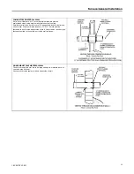
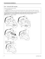
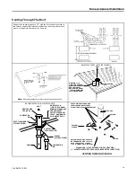
Venting Through The Roof
Support Horizontal pipe every 3’0” with the first support as close to
the furnace as possible. Induced draft blower, housing, and furnace
must not support the weight of the flue pipe.
Note:
All measurements are from centerline to centerline.
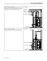
BAYAIR30AVENTA / BAYAIR30CNVENT
MAINTAIN 12 IN.
(18 IN. FOR CANADA)
MINIMUM CLEARANCE
ABOVE HIGHEST
ANTICIPATED SNOW
LEVEL. MAXIMUM OF
24 IN. ABOVE ROOF.
VENT
COMBUSTION
AIR
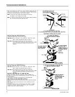
BAYAIR30AVENTA / BAYAIR30CNVENT
REMOVE RIBS
FROM CAP
COMBUSTION
AIR
ROOF FLASHING BOOT
(FIELD SUPPLIED)
COMBUSTION
AIR
VENT
ELBOW
(FIELD SUPPLIED)
MAINTAIN 12 IN.
(18 IN. FOR CANADA)
MINIMUM CLEARANCE
ABOVE HIGHEST
ANTICIPATED SNOW
LEVEL. MAXIMUM OF
24 IN. ABOVE ROOF
SUPPORT
(FIELD SUPPLIED)
VENT
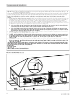
GALVANIZED FIRESTOP SHOULD
BE FABRICATED WITH 3-7/8" DIA.
HOLE FOR SUPPORT FLANGE
(12" x 12" PANEL OR 12" DIA MIN.)
VENTING THROUGH CEILING
CEILING
SUPPORT
FLANGE
FLUE PIPE
COUPLING
SEAL BETWEEN FLANGE, PIPE,
COUPLING AND METAL PANEL
WITH HI TEMP RTV SILICONE SEALANT
CLEARANCE ( 0" ACCEPTABLE FOR PVC VENT PIPE )
( 1" ACCEPTABLE FOR TYPE 29-4C STAINLESS STEEL VENT PIPE )
F
Fu
urrn
na
acce
e G
Ge
en
ne
erra
all IIn
nsstta
alllla
attiio
on
n
Summary of Contents for S9V2B040D3PSBA
Page 12: ...12 18 CE01D1 1F EN Outline Drawings...
Page 13: ...18 CE01D1 1F EN 13 O Ou ut tl li in ne e D Dr ra aw wi in ng gs s...
Page 14: ...14 18 CE01D1 1F EN O Ou ut tl li in ne e D Dr ra aw wi in ng gs s...
Page 15: ...18 CE01D1 1F EN 15 O Ou ut tl li in ne e D Dr ra aw wi in ng gs s...
Page 16: ...16 18 CE01D1 1F EN O Ou ut tl li in ne e D Dr ra aw wi in ng gs s...
Page 17: ...18 CE01D1 1F EN 17 O Ou ut tl li in ne e D Dr ra aw wi in ng gs s...

