Operating & Maintenance Manual
38
22478341 (1-15-07) Rev A
Maintenance
CAUTION
!
Any unauthorized modification or
failure to maintain this equipment may
make it unsafe and out of factory
warranty.
If performing more than visual
inspections, disconnect battery
cables and open manual blowdown
valve.
Use extreme care to avoid contacting
hot surfaces (engine exhaust manifold
and piping, air receiver and air
discharge piping, etc.).
Never operate this machine with any
guards removed.
Inch and metric hardware was used in
the design and assembly of this unit.
Consult the parts manual for
clarification of usage.
NOTICE
Disregard any maintenance pertaining
to components not provided on your
machine.
General
In addition to periodic inspections, many of
the components in these units require
periodic servicing to provide maximum
output and performance. Servicing may
consist of pre-operation and post-operation
procedures to be performed by the operating
or maintenance personnel. The primary
function of preventive maintenance is to
prevent failure, and consequently, the need
for repair. Preventive maintenance is the
easiest and the least expensive type of
maintenance. Maintaining your unit and
keeping it clean at all times will facilitate
servicing.
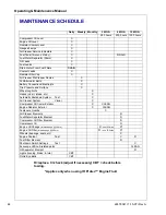
Scheduled Maintenance
The maintenance schedule is based on
normal operation of the unit. This page can
be reproduced and used as a checklist by the
service personnel. In the event unusual
environmental operating conditions exist, the
schedule should be adjusted accordingly.
Compressor Oil Level
Check the compressor fluid level when the
machine is not operating. Maintain the fluid
level between bottom and midway of the
sight glass on the separator tank.
Air Cleaner
If this unit is equipped with the Optional
Diagnostic Panel, it has an AIR FILTERS
RESTRICTED lamp on the instrument panel,
covering both the engine and the
compressor.
This should be checked daily during
operation. If the lamp glows (red) with the
unit operating at full speed, servicing of the
cleaner element is necessary.
Also weekly squeeze the rubber valve
(precleaner dirt dump) on each air cleaner
housing to ensure that they are not clogged.
The air filters restricted sensor will
automatically reset after the main power
switch is turned to “OFF.”
To service the air cleaners on all units
proceed as follows:
1. Loosen outer wing nut and remove with
Summary of Contents for P250WJD
Page 5: ...22478341 1 15 07 Rev A 3 FOREWORD ...
Page 8: ...6 22478341 1 15 07 Rev A Always use Ingersoll Rand Replacement parts ...
Page 9: ...22478341 1 15 07 Rev A 7 DRAWBAR NOTICE ...
Page 11: ...22478341 1 15 07 Rev A 9 SAFETY ...
Page 15: ...SAFETY Operating Maintenance Manual 22478341 1 15 07 Rev A 13 ...
Page 16: ...Operating Maintenance Manual SAFETY 14 22478341 1 15 07 Rev A ...
Page 18: ...Operating Maintenance Manual SAFETY 16 22478341 1 15 07 Rev A ...
Page 19: ...SAFETY Operating Maintenance Manual 22478341 1 15 07 Rev A 17 ...
Page 21: ...22478341 1 15 07 Rev A 19 NOISE EMISSION ...
Page 27: ...22478341 1 15 07 Rev A 25 GENERAL DATA ...
Page 30: ...28 22478341 1 15 07 Rev A Always use Ingersoll Rand Replacement parts ...
Page 31: ...22478341 1 15 07 Rev A 29 OPERATION ...
Page 38: ...36 22478341 1 15 07 Rev A Always use Ingersoll Rand Replacement parts ...
Page 39: ...22478341 1 15 07 Rev A 37 MAINTENANCE ...
Page 47: ...22478341 1 15 07 Rev A 45 LUBRICATION ...
Page 49: ...22478341 1 15 07 Rev A 47 TROUBLE SHOOTING ...
Page 56: ...54 22478341 1 15 07 Rev A Always use Ingersoll Rand Replacement parts ...

