


MAINTENANCE
Operating & Maintenance Manual
22478341 (1-15-07) Rev A
39
cover. Remove Element.
2. Inspect air cleaner housing for any
condition that might cause a leak and
correct as necessary.
3. Wipe inside of air cleaner housing with a
clean, damp cloth to remove any dirt
accumulation, especially in the area
where the element seals against the
housing.
4. Install new elements in the reverse order
to the above. Tighten wing nut firmly.
5. Inspect to ensure that end cap seals
tightly 360° around air cleaner body.
In addition, the air cleaner system (housing
and piping) should be inspected every month
for any leakage paths or inlet obstructions.
Make sure the air cleaner mounting bolts and
clamps are tight. Check the air cleaner
housing for dents or damage which could
lead to a leak. Inspect the air transfer tubing
from the air cleaner to the compressor and
the engine for leaks.
Make sure that all clamps and flange joints
are tight.
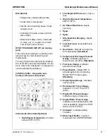
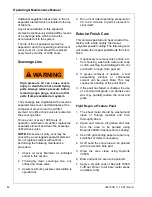
Gauges
The instruments or gauges are essential for
safety, maximum productivity and long
service life of the machine. Inspect the
gauges and test any diagnostic lamps prior to
start-up. During operation observe the
gauges and any lamps for proper functioning.
Refer to Operating Controls, for the normal
readings.
Fuel Tank
CLEAN fuel in the fuel tanks is vitally
important and every precaution should be
taken to ensure that only clean fuel is poured
or pumped into the tank.
When filling the fuel tank on this unit, by
methods other than a pump and hose, use a
CLEAN non-metallic funnel.
Battery
Keep the battery posts-to-cable connections
clean, tight and lightly coated with a grease.
Also the electrolyte level in each cell should
cover the top of the plates. If necessary, top-
up with clean distilled water.
Tires
A weekly inspection is recommended. Tires
that have cuts or cracks or little tread should
be repaired or replaced. Monthly check the
wheel lug nuts for tightness.
Fasteners
Visually check entire unit in regard to bolts,
nuts and screws being properly secured.
Spot check several capscrews and nuts for
proper torque. If any are found loose, a more
thorough inspection must be made. Take
corrective action.
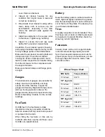
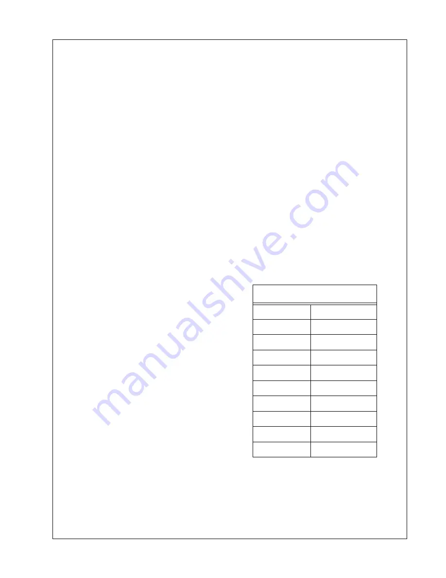
Wheel Torque Chart
M12 bolts
Torque (ft-Lbs)
13” wheel
60-70
1/2” lug nuts
13” wheel
80-90
15” wheel
105-115
16” wheel
105-115
16.5” wheel
105-115
5/8” lug nuts
16” wheel
190-210
17.5” wheel
190-210
Summary of Contents for P250WJD
Page 5: ...22478341 1 15 07 Rev A 3 FOREWORD ...
Page 8: ...6 22478341 1 15 07 Rev A Always use Ingersoll Rand Replacement parts ...
Page 9: ...22478341 1 15 07 Rev A 7 DRAWBAR NOTICE ...
Page 11: ...22478341 1 15 07 Rev A 9 SAFETY ...
Page 15: ...SAFETY Operating Maintenance Manual 22478341 1 15 07 Rev A 13 ...
Page 16: ...Operating Maintenance Manual SAFETY 14 22478341 1 15 07 Rev A ...
Page 18: ...Operating Maintenance Manual SAFETY 16 22478341 1 15 07 Rev A ...
Page 19: ...SAFETY Operating Maintenance Manual 22478341 1 15 07 Rev A 17 ...
Page 21: ...22478341 1 15 07 Rev A 19 NOISE EMISSION ...
Page 27: ...22478341 1 15 07 Rev A 25 GENERAL DATA ...
Page 30: ...28 22478341 1 15 07 Rev A Always use Ingersoll Rand Replacement parts ...
Page 31: ...22478341 1 15 07 Rev A 29 OPERATION ...
Page 38: ...36 22478341 1 15 07 Rev A Always use Ingersoll Rand Replacement parts ...
Page 39: ...22478341 1 15 07 Rev A 37 MAINTENANCE ...
Page 47: ...22478341 1 15 07 Rev A 45 LUBRICATION ...
Page 49: ...22478341 1 15 07 Rev A 47 TROUBLE SHOOTING ...
Page 56: ...54 22478341 1 15 07 Rev A Always use Ingersoll Rand Replacement parts ...