22
INFOSEC UPS SYSTEM - 4, rue de la Rigotière - 44700 Orvault - FRANCE - www.infosec-ups.com
Hot Line – Tel + 33 (0)2 40 76 15 82 - Fax + 33 (0)2 40 94 29 51 - [email protected] – 03 11 AA AA 201 18
Communication protocol of the RS-232.
The communication protocol used is a “MASTER/SLAVE” type. The computer or computer system (“MASTER”)
asks for certain data, and the UPS (“SLAVE”) answers immediately with the required data.
Firstly, the computer communication channel will be programmed with the same parameters as the UPS
communication channel.
Then the communication can begin and the UPS is sent the first question.
If a problem occurs during the communication, it is advisable to repeat the channel initialisation sequence.
Physical structure of the RS-485.
Unlike other serial communication links, this uses only 2 wires (pins 4 and 9 of the female DB9 connector) to
perform the dialogue between the systems connected to the network. The communication will be established
by sending and receiving signals in differential mode, which gives the system great immunity to noise and a
long reach (approx. 800 m).
Pin-out
-
Pin 4. RS-485 output signal A (+).
-
Pin 9. RS-485 output signal B (–)²².
Communication protocol of the RS-485.
The communication protocol of the RS-485 channel is developed to enable the UPS to dialogue with other
computer systems that have this kind of channel.
The RS-232 and RS-485 communication parameters are as follows:
Communication speed: 1200, 2400, 4800, 9600 or 19200 Bauds.
No. information bits: 8 Bits.
No. stop bits: 1 or 2 stop bits.
Parity: - Even, Odd or None.
4.3.8
EPO terminals (X50).
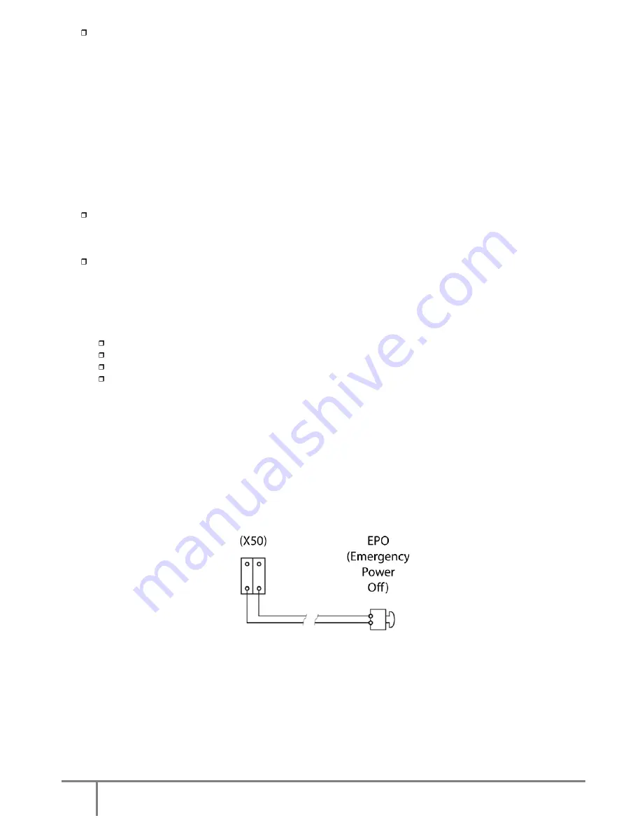
The equipment has two terminals ready for external (remote) Emergency Power Off (EPO).
If a switch or button (EPO) has to be installed, the cable bridge that closes the circuit has to be removed from
terminal strip (X50).
The switch or button (EPO) has to open the circuit between the terminal strip (X50) to activate the emergency
shutdown. To restore the UPS to normal mode, invert the position of the switch or button (EPO), and close the
circuit in terminal strip (X50).
For information on EPO operation, see section 5.3 of this manual.
Fig.17.
Terminals for connecting an external push-button (EPO), property of the user.
Summary of Contents for M4T
Page 1: ...User Manual 10 80 kVA ...


