INFOSEC UPS SYSTEM - 4, rue de la Rigotière - 44700 Orvault - FRANCE - www.infosec-ups.com
Hot Line – Tel + 33 (0)2 40 76 15 82 - Fax + 33 (0)2 40 94 29 51 - [email protected] – 03 11 AA AA 201 18
21
4.3.6
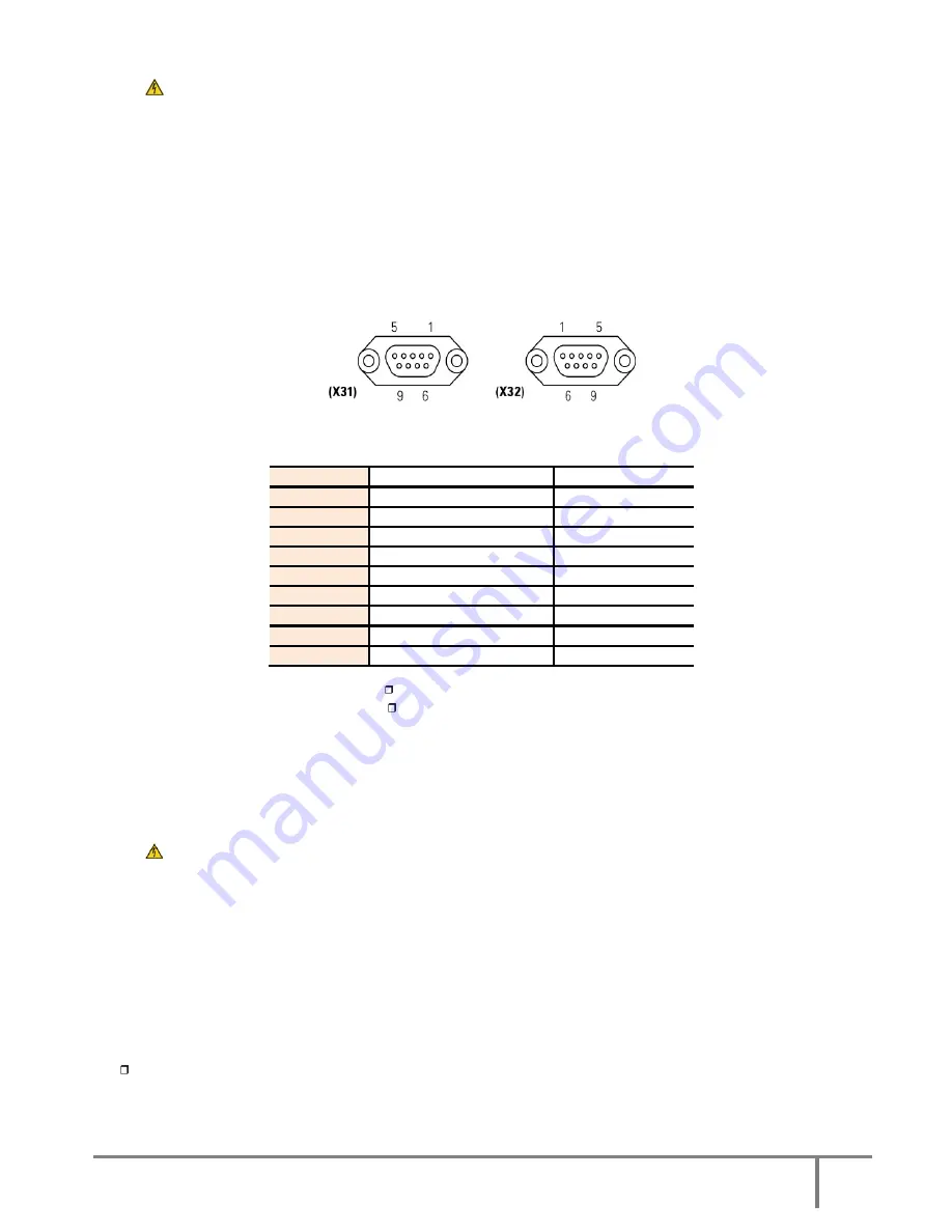
COM port to relay. Connector (X32).
The communications line (COM) represents a very low safety voltage circuit. To maintain the quality, it
must be installed away from other lines that have dangerous voltages (power distribution line).
The communication port to relays provides digital signals in the form of potential free contacts with a
maximum applicable voltage and current of 6 A 30 V DC or 6 A 100 V AC. Both channels are used to
connect the UPS to any machine or device that has this standard bus (connector DB9 (X32)).
In standard units, there are 5 output signalling relays (one of which can be configured), whose common
point is connected to pin 5. Also an input signal can be externally supplied to perform Shutdown (5V~12V).
The most common use of these kinds of port is to supply the necessary information to the file closing
software.
Fig.16.
DB9 Connector (X31) & (X32).
Pin-out No.
Description
N.C.-N.O. Position
1 Shutdown
signal
+
-
2 Shutdown
signal
–
-
3 Configurable Not
connected
4
Discharge - Mains failure
N.C.
5 Common
-
6 Equipment
in
Bypass
N.O.
7 Low
battery N.O.
8 General
alarm N.O.
9
Discharge - Mains failure
N.O.
N.C.: Normally closed contact.
N.O.: Normally open contact.
Table 2.
Alarm interface to relay connector DB9
(X32).
4.3.7
Port COM RS-232 & RS-485. Connector (X32).
The communications line (COM) represents a very low safety voltage circuit. To maintain the quality, it
must be installed away from other lines that have dangerous voltages (power distribution line).
Both of the equipment’s communication ports, RS-232 and RS-485, are in the same connector DB9. It is not
possible to use them simultaneously.
Both channels are in use to connect the UPS with any machine or device that has this standard bus. The
RS-232 transmits serial data, so it is possible to send a large amount of information through a
communication cable with just 3 wires.
Physical structure of the RS-232.
Pin-out
-
Pin 2. RXD. Serial data reception.
-
Pin 3. TXD. Serial data transmission.
-
Pin 5. GND. Signal mass.
Summary of Contents for M4T
Page 1: ...User Manual 10 80 kVA ...


