Quanta 5
Quanta 5 Technical User Manual
67
Parameter
Description
Unit role
One units must be set to Master and the other one to Slave.
Please note that the following settings must be equal for "master" and "slave"
unit to establish the radio link:
Center frequency - there are two ways:
Manually via "Downlink center frequency" and "Uplink center
frequency" parameters. In this case wireless link will be setup at
once.
Automatically with "Automatic selection of center frequency"
function. In this case frequency channel grids must be set on
both units. At the initial phase Master unit will select its center
frequency automatically from grid, after that Slave unit will scan
frequencies from its grid and wireless link will be established
when Slave will find the center frequency which Master operates
on.
Channel width - should be the same and set manually on both units.
When a wireless link has been established Slave unit will continuously inherit
radio frontend parameters from Master unit excluding frequency channel grids.
So, if you change some values on Master they will be set on Slave
automatically.
Fixed center
frequency
Available only on the Slave unit.
Enabled - center frequency must be set manually on wich the Slave unit
will operate.
Disabled - center frequenct will be selected automatically based on
frequency channel grids.
Automatic
selection of
center
frequency
There are several way to define center frequencies in Quanta 5:
Frequency selection off - center frequency will be set manually.
DFS and radar detection - center frequency will be set automatically
according to frequency channel grids. In this mode Master unit will
switch to the different frequency if high level interference or radar will
be detected. Slave unit will switch too after some time.
Summary of Contents for Quanta 5
Page 1: ...Quanta 5 Technical User Manual ...
Page 37: ...Quanta 5 Quanta 5 Technical User Manual 37 ...
Page 48: ...Quanta 5 Quanta 5 Technical User Manual 48 Figure AUX ODU LPU G Assembly Scheme ...
Page 52: ...Quanta 5 Quanta 5 Technical User Manual 52 Figure AUX ODU LPU G Cable Gland Assembly Scheme ...
Page 54: ...Quanta 5 Quanta 5 Technical User Manual 54 ...
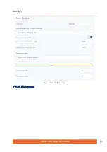
Page 69: ...Quanta 5 Quanta 5 Technical User Manual 69 Figure Radio frontend settings 7 5 2 Air frame ...
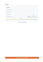
Page 71: ...Quanta 5 Quanta 5 Technical User Manual 71 Figure Air frame settings ...
Page 77: ...Quanta 5 Quanta 5 Technical User Manual 77 ...
Page 98: ...Quanta 5 Quanta 5 Technical User Manual 98 9 Glossary ...
Page 100: ...Quanta 5 Quanta 5 Technical User Manual 100 ...


